Asus H170I-PRO/CSM User Guide - Page 14
RTC Battery header 2-pin BATT_CON, Serial port connector 10-1 pin COM
 |
View all Asus H170I-PRO/CSM manuals
Add to My Manuals
Save this manual to your list of manuals |
Page 14 highlights
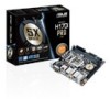
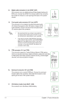
13. Digital audio connector (4-1 pin SPDIF_OUT) This connector is for an additional Sony/Philips Digital Interface (S/ PDIF) port. Connect the S/PDIF Out module cable to this connector, then install the module to a slot opening at the back of the system chassis. +5V SPDIFOUT GND SPDIF_OUT 14. Front panel audio connector (10-1 pin AAFP) AGND NC SENSE1_RETUR SENSE2_RETUR This connector is for a chassis-mounted front panel audio I/O module that supports either HD Audio or legacy AC`97 audio standard. Connect one end of the front panel audio I/O module cable to this connector. AAFP PIN 1 AGND NC NC NC MIC2 MICPWR Line out_R NC Line out_L PORT1 L PORT1 R PORT2 R SENSE_SEND PORT2 L • We recommend that you connect a high-definition front panel audio module to this connector to avail of the motherboard's high-definition audio capability. • If you want to connect a high-definition front panel audio module to this connector, set the Front Panel Type item in the BIOS setup to [HD]. If you want to connect an AC'97 front panel audio module to this connector, set the item to [AC97]. By default, this connector is set to [HD]. HD-audio-compliant Legacy AC'97 pin definition compliant definition 15. TPM connector (14-1 pin TPM) PWRDWN F_SERIRQ F_FRAME# F_LAD3 F_LAD2 F_LAD1 F_LAD0 This connector supports a Trusted Platform Module (TPM) system, which can securely store keys, digital certificates, passwords, and data. TPM A TPM system also helps enhance network security, protects digital identities, and ensures platform integrity. PIN 1 +3VSB S_PCIRST#_TBD GND C_PCICLK_TPM +3V +3V 16. Serial port connector (10-1 pin COM) This connector is for a serial (COM) port. Connect the serial port module cable to this connector, then install the module to a slot opening at the back of the system chassis. 17. RTC Battery header (2-pin BATT_CON) This connector is for the lithium CMOS battery. DCD TXD GND RTS RI RXD DTR DSR CTS COM PIN 1 BATT_CON VBAT GND PIN 1 1-6 Chapter 1: Product introduction
-
 1
1 -
2
-
3
-
4
-
5
-
6
-
7
-
8
-
 9
9 -
 10
10 -
 11
11 -
 12
12 -
 13
13 -
 14
14 -
 15
15 -
 16
16 -
 17
17 -
 18
18 -
 19
19 -
20
-
21
-
22
-
23
-
24
-
25
-
26
-
27
-
28
-
29
-
30
-
31
-
32
-
33
-
34
-
35
-
36
-
37
 |
 |
