Asus N100I-EM-A Users Manual English - Page 9
Motherboard layout
 |
View all Asus N100I-EM-A manuals
Add to My Manuals
Save this manual to your list of manuals |
Page 9 highlights
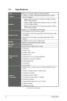
2.2 Motherboard layout NOTE: Place four screws into the holes indicated by circles to secure the motherboard to the chassis. CAUTION! Do not overtighten the screws! Doing so can damage the motherboard. 1 30 29 DC_PWR1 DC_PWR2 HDMI 23 4 5 17.0cm(6.7in) U32G1_34 DDR4 So-DIMM_A (64bit, 204-pin module) PANEL_SW BKLTEN_SEL VCC_PWR SEL COM3 COM2 VGA COM1 COM1_SEL 28 Place this side towards the rear of the chassis 27 26 25 USB_7 256Mb BIOS Intel® N100 LAN2_U32G1_12 LAN1_USB_56 RTL TPM 8111H RTL 8111H Super I/O (BOTTOM) CLRTC M.2_(SOCKET3) AUDIO BATTERY M.2(WIFI) F_AUDIO ALC I2C 897 AT_ATX_SEL GPIO_CON 2280 COM_DEBUG SPK_OUT PCIEX1(G3) COM4 2260 2242 COM5 COM6 SPEAKER F_PANEL CHASSIS 24 23 22 21 20 19 18 17 16 15 SATA6G_1 SATA6G_2 SATA_PWR2 SATA_PWR1 CHA_FAN LVDS_EDP 17.0cm(6.7in) LCD_BLKT_PANEL 6 7 8 9 10 11 12 13 14 NOTE: The audio codec may vary between motherboards, please consult your sales window for the motherboards' exact codec type. 2-2 N100I-EM-A
-
 1
1 -
2
-
3
-
 4
4 -
 5
5 -
 6
6 -
 7
7 -
 8
8 -
 9
9 -
 10
10 -
 11
11 -
 12
12 -
 13
13 -
 14
14 -
15
-
16
-
17
-
18
-
19
-
20
-
21
-
22
-
23
-
24
-
25
-
26
-
27
-
28
-
29
-
30
-
31
-
32
-
33
-
34
-
35
-
36
-
37
-
38
-
39
-
40
-
41
-
42
-
43
-
44
-
45
-
46
-
47
-
48
-
49
-
50
-
51
-
52
-
53
-
54
-
55
 |
 |
