Asus P I-P65UP8 CP6ND User Manual - Page 26
hard drive bootup see HDD Sequence SCSI/IDE First in the BIOS FEA
 |
View all Asus P I-P65UP8 CP6ND manuals
Add to My Manuals
Save this manual to your list of manuals |
Page 26 highlights
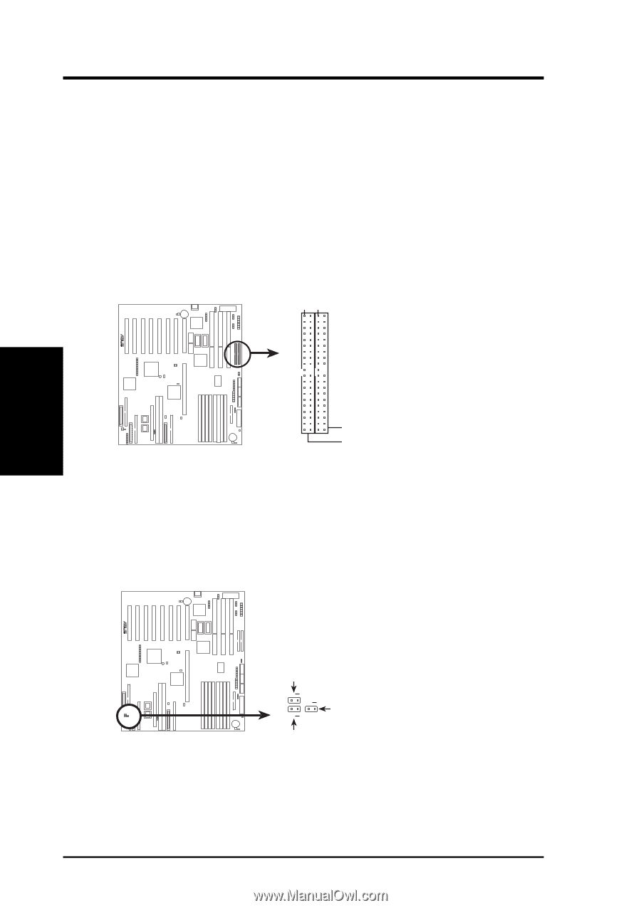
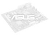
R R III. INSTALLATION (Connectors) III. INSTALLATION 5. Primary/Secondary IDE Connectors (Two 40-1 pin IDE1 & IDE2) These connectors support the provided IDE hard disk ribbon cable. After connecting the single end to the board, connect the two plugs at the other end to your hard disk(s). If you install two hard disks on one connector (channel), then you must configure a second drive as Slave mode by setting its jumper according to your hard disk jumper diagram. You may also configure two hard disks to be both Masters using one ribbon cable on the primary IDE connector and another on the secondary IDE connector. A new BIOS feature allows SCSI hard drive bootup (see "HDD Sequence SCSI/IDE First" in the BIOS FEATURES SETUP of the BIOS software). (Pin 20 is removed to prevent inserting in the wrong orientation when using ribbon cables with pin 20 plugged). Pin 1 Orient the red stripe on the IDE ribbon cable to Pin 1 IDE (Hard Disk Drive) Connectors Secondary IDE Connector Primary IDE Connector 6. SCSI and IDE Activity LED (2-pin HD LED) This connector connects to the hard disk activity indicator light on the system cabinet. Read and write activity by devices connected to the Primary or Secondary IDE connectors will cause the HD LED to light. IDE Activity LED Lead TIP: If the case-mounted LED does not light, try reversing the 2-pin plug. HD LED A (for Symbios Ch A) + + + HD LED (for Adaptec and IDE) HD LED B (for Symbios Ch B) 26 ASUS P/I-P65UP8 User's Manual
-
 1
1 -
2
-
3
-
4
-
5
-
6
-
7
-
8
-
9
-
10
-
11
-
12
-
13
-
14
-
15
-
16
-
17
-
18
-
19
-
20
-
 21
21 -
 22
22 -
 23
23 -
 24
24 -
 25
25 -
 26
26 -
 27
27 -
 28
28 -
 29
29 -
 30
30 -
 31
31 -
32
-
33
-
34
-
35
-
36
-
37
-
38
-
39
-
40
 |
 |