Asus P2-99 P2-99 User Manual - Page 13
Iii. H/w Setup - memory
 |
View all Asus P2-99 manuals
Add to My Manuals
Save this manual to your list of manuals |
Page 13 highlights
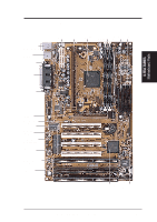
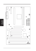
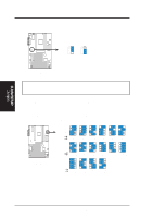
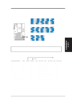
III. H/W SETUP Layout Contents III. HARDWARE SETUP Motherboard Settings 1) AGPFS 2) KBPWR 3) VIO 4) VCORE 5) FS0, FS1, FS2, FS3 6) BF0, BF1, BF2, BF3 p. 14 AGP Bus Frequency Setting p. 15 Keyboard Power Up Setting (Disable/Enable) p. 15 I/O Voltage Setting (Normal/Test) p. 16 Core Voltage Setting (Normal/Test) p. 16 CPU External Clock (BUS) Frequency Selection p. 17 CPU Core:BUS Frequency Multiple Expansion Slots/Sockets 1) System Memory p. 18 System Memory Support 2) DIMM1, DIMM2 p. 19 DIMM Memory Module Support 3) Slot 1 p. 21 CPU Support 4) SLOT1, SLOT2, SLOT3 p. 26 16-bit ISA Bus Expansion Slots* 5) PCI1,PCI2,PCI3,PCI4 p. 26 32-bit PCI Bus Expansion Slots 6) AGP p. 27 Accelerated Graphics Port Hardware Monitor (optional) 1) JTPWR, JTCPU p. 25 Thermal Sensor Connectors Connectors 1) PS2KBMS p. 28 PS/2 Mouse Port Connector (6 pin-female) 2) PS2KBMS p. 28 PS/2 Keyboard Port Connector (6-pin female) 3) PARALLEL p. 29 Parallel (Printer) Port Connector (25-pin female) 4) COM1, COM2 p. 29 Serial Port COM1 & COM2 (two 9-pin male) 5) USB p. 29 Universal Serial BUS Port Connectors 1 & 2 (Two 4-pin female) 6) Primary/Secondary IDE p. 30 Primary/Secondary IDE Connectors (Two 40-1 pins) 7) FLOPPY p. 30 Floppy Drive Port Connector (34 pins) 8) IDELED p. 31 IDE LED Activity Light (2 pins) 9) WOR p. 31 Wake-On-Ring Connector (2 pins) 10) CHA_, PWR_, CPU_FAN p. 32 Chassis, Power Supply, CPU Fan Power Lead (3 pins) 11) WOL_CON p. 33 Wake-On-LAN Connector (3 pins) 12) IR p. 33 Infrared Port Module Connector (5 pins) 13) SBLINK p. 34 SB-Link™ Port Connector (6-1 pins) 14) SMB CON. p. 34 SMBus Connector (3 pins) 15) ATXPWR p. 35 ATX Motherboard Power Connector (20 pins) 16) CHASIS p. 35 Chassis Intrusion Alarm Lead (4-1 pins) 17) PWR.LED (PANEL) 18) KEYLOCK (PANEL) 19) SPEAKER (PANEL) 20) MSG.LED (PANEL) 21) SMI (PANEL) 22) PWR.SW (PANEL) 23) RESET (PANEL) p. 36 System Power LED Lead (3-1 pins) p. 36 Keyboard Lock Switch Lead (2 pins) p. 36 System Warning Speaker Connector (4 pins) p. 36 System Message LED (2 pins) p. 36 System Management Interrupt Lead (2 pins) p. 36 ATX Power / Soft-Off Switch Lead (2 pins) p. 36 Reset Switch Lead (2 pins) *The optional onboard hardware monitor uses the address 290H-297H so legacy ISA cards must not use this address otherwise conflicts will occur. ASUS P2-99 User's Manual 13
-
 1
1 -
2
-
3
-
4
-
5
-
6
-
7
-
 8
8 -
 9
9 -
 10
10 -
 11
11 -
 12
12 -
 13
13 -
 14
14 -
 15
15 -
 16
16 -
 17
17 -
 18
18 -
19
-
20
-
21
-
22
-
23
-
24
-
25
-
26
-
27
-
28
-
29
-
30
-
31
-
32
-
33
-
34
-
35
-
36
-
37
-
38
-
39
-
40
-
41
-
42
-
43
-
44
-
45
-
46
-
47
-
48
-
49
-
50
-
51
-
52
-
53
-
54
-
55
-
56
-
57
-
58
-
59
-
60
-
61
-
62
-
63
-
64
-
65
-
66
-
67
-
68
-
69
-
70
-
71
-
72
-
73
-
74
-
75
-
76
-
77
-
78
-
79
-
80
-
81
-
82
-
83
-
84
-
85
-
86
-
87
-
88
-
89
-
90
-
91
-
92
-
93
-
94
-
95
-
96
 |
 |
