Asus P4P800-MX P4P800-MX user's manual - Page 35
Chassis intrusion connector 4-1 pin CHASSIS1, Optional GAME/MIDI connector 16-1 pin GAME1
 |
View all Asus P4P800-MX manuals
Add to My Manuals
Save this manual to your list of manuals |
Page 35 highlights
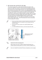
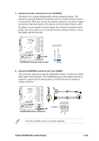
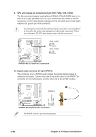
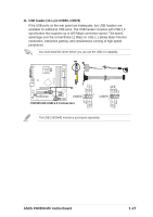
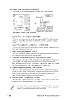
7. Chassis intrusion connector (4-1 pin CHASSIS1) This lead is for a chassis designed with intrusion detection feature. This requires an external detection mechanism such as a chassis intrusion sensor or microswitch. When you remove any chassis component, the sensor triggers and sends a high-level signal to this lead to record a chassis intrusion event. By default, the pins labeled "Chassis Signal" and "Ground" are shorted with a jumper cap. If you wish to use the chassis intrusion detection feature, remove the jumper cap from the pins. P4P800-MX +5VSB_MB Chassis Signal GND CHASSIS1 ® P4P800-MX Chassis Alarm Lead (Default) 8. Optional GAME/MIDI connector (16-1 pin GAME1) This connector supports an optional GAME/MIDI module. Connect the GAME/ MIDI cable to this connector. The GAME/MIDI port on the module connects a joystick or a game pad for playing games, and MIDI devices for playing or editing audio files. P4P800-MX +5V J1B2 J1CY GND GND J1CX J1B1 +5V ® P4P800-MX Game Connector GAME1 The USB 2.0/GAME module is purchased separately. ASUS P4P800-MX motherboard MIDI_IN J2B2 J2CY MIDI_OUT J2CX J2B1 +5V 1-25
-
 1
1 -
2
-
3
-
4
-
5
-
6
-
7
-
8
-
9
-
10
-
11
-
12
-
13
-
14
-
15
-
16
-
17
-
18
-
19
-
20
-
21
-
22
-
23
-
24
-
25
-
26
-
27
-
28
-
29
-
 30
30 -
 31
31 -
 32
32 -
 33
33 -
 34
34 -
 35
35 -
 36
36 -
 37
37 -
 38
38 -
 39
39 -
 40
40 -
41
-
42
-
43
-
44
-
45
-
46
-
47
-
48
-
49
-
50
-
51
-
52
-
53
-
54
-
55
-
56
-
57
-
58
-
59
-
60
-
61
-
62
-
63
-
64
-
65
-
66
-
67
-
68
-
69
-
70
-
71
-
72
 |
 |
