Asus P4P8X SE P4P8X SE user's manual English version E1479 - Page 17
ASUS P4P8X SE motherboard user guide - rom
 |
View all Asus P4P8X SE manuals
Add to My Manuals
Save this manual to your list of manuals |
Page 17 highlights
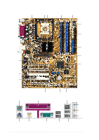
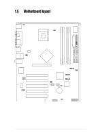
1 ATX 12V connector. This power connector connects the 4-pin 12V plug from the ATX 12V power supply. 2 CPU socket. A 478-pin surface mount, Zero Insertion Force (ZIF) socket for the Intel® Pentium® 4 Processor, with 800*/533/400 MHz system bus that allows 4.3GB/s, and 3.2GB/s data transfer rates, respectively. (*Overclocking mode) 3 North bridge controller. The Intel® 82865P Memory Controller Hub (MCH) provides the processor interface with 533/400 MHz frequency, system memory interface at 333/266MHz operation and an AGP interface that supports AGP 3.0 specification including 8X Fast Write protocol. The MCH interconnects to the south bridge ICH5 via the Intel® proprietary Hub Interface. 4 DDR DIMM sockets. These four 184-pin DIMM sockets support up to 4GB system memory using unbuffered non-ECC PC3200*/2700/2100 DDR DIMMs. (*Overclocking mode) 5 ATX power connector. This 20-pin connector connects to an ATX power supply. The power supply must have at least 1A on the +5V standby lead (+5VSB). 6 Super I/O controller. This Winbond Low Pin Count (LPC) interface provides the commonly used Super I/O functionality. The chipset supports a highperformance floppy disk controller for a 360K/720K/1.44M/2.88M floppy disk drive, a multi-mode parallel port, two standard compatible UARTs, and a Flash ROM interface. This controller also integrates the ASIC for PC health monitoring. 7 Floppy disk connector. This connector accommodates the provided ribbon cable for the floppy disk drive. One side of the connector is slotted to prevent incorrect insertion of the floppy disk cable. 8 IDE connectors. These dual-channel bus master IDE connectors support Ultra DMA100/66, PIO Modes 3 & 4 IDE devices. Both the primary (blue) and secondary (black) connectors are slotted to prevent incorrect insertion of the IDE ribbon cable. 9 AGP 8X slot. This Accelerated Graphics Port (AGP) slot supports 0.8V/1.5V AGP 8X mode graphics cards for 3D graphical applications. 10 SATA connectors. These connectors support Serial ATA HDDs and allows for up to 150MB/s data transfer rate, faster than the standard Parallel ATA with 133 MB/s. 11 Flash ROM. This 4Mb firmware contains the programmable BIOS program. 12 South bridge controller. The fifth-generation Intel I/O Controller Hub (ICH5) is a subsystem that integrates various I/O functions including 2-channel ATA100 bus master IDE controller, up to eight USB 2.0/1.1 ports, I/O APIC, SMBus 2.0 controller, LPC interface, AC'97 2.2 interface, and PCI 2.2 interface. The ICH5 also contains the necessary arbitration and buffering for efficient utilization of these interfaces. 13 Standby power LED. This LED lights up if there is a standby power on the motherboard. This LED acts as a reminder to turn off the system power before plugging or unplugging devices. ASUS P4P8X SE motherboard user guide 1-7
-
 1
1 -
2
-
3
-
4
-
5
-
6
-
7
-
8
-
9
-
10
-
11
-
 12
12 -
 13
13 -
 14
14 -
 15
15 -
 16
16 -
 17
17 -
 18
18 -
 19
19 -
 20
20 -
 21
21 -
 22
22 -
23
-
24
-
25
-
26
-
27
-
28
-
29
-
30
-
31
-
32
-
33
-
34
-
35
-
36
-
37
-
38
-
39
-
40
-
41
-
42
-
43
-
44
-
45
-
46
-
47
-
48
-
49
-
50
-
51
-
52
-
53
-
54
-
55
-
56
-
57
-
58
-
59
-
60
-
61
-
62
-
63
-
64
-
65
-
66
-
67
-
68
-
69
-
70
-
71
-
72
-
73
-
74
-
75
-
76
-
77
-
78
 |
 |