Asus P4P8X SE P4P8X SE user's manual English version E1479 - Page 26
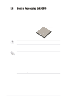
Installing a DIMM
 |
View all Asus P4P8X SE manuals
Add to My Manuals
Save this manual to your list of manuals |
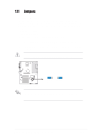
Page 26 highlights
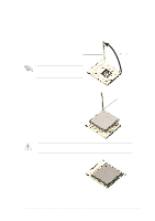
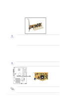
Table 3 DDR400 Qualified Vendor List (QVL) (Overclocked Mode) Size 512MB 256MB 256MB 512MB 256MB 512MB 256MB 512MB 256MB 256MB 256MB 256MB 256MB 512MB 256MB 256MB 512MB 256MB 512MB 256MB 512MB 512MB 256MB Vendor P/N Number TwinMOS M2G9J16AGATT9F081AA4T TwinMOS M2S9I08AFAPS9F0811A-T Apacer 77.10636.465 Apacer 77.10736.464 Transcend TS32MLD64V4F3 Transcend TS64MLD64V4F3 Transcend TS32MLD64V4F3 Transcend TS64MLD64V4F3 A DATA MDOAD5F3G315B1ECZ A DATA MDOSS6F3G31JB1EAE A DATA MDOWB5F3G316B1EAE KINGSTON KVR400X64C25/256 Winbond W9425GCDB-5 Winbond W9451GCDB-5 Infineon HYS64D16301GU-5-B Infineon HYS64D32300GU-5-B Infineon HYS64D64320GU-5-B SAMSUNG M368L3223ETM-CCC SAMSUNG M368L6432ETM-CCC Hynix HYMD232646B8J-D43 AA Hynix HYMD264646B8J-D43 AA MICRON MT16VDDT6464AG-40BC4 MICRON MT8VDDT3264AG-40BC4 DS/SS DS SS SS DS SS DS SS DS SS SS SS SS SS DS SS SS DS SS DS SS DS DS SS Component TMD7608F8E50D A2S56D30ATP K4H560838D-TCC4 K4H560838D-TCC4 K4H560838D-TCC4 K4H560838D-TCC4 V58C2256804SAT5 V58C2256804SAT5 ADD8608A8A-5B K4H560838D-TCC4 W942508BH-5 W942508BH-5 W942508BH-5 W942508BH-5 HYB25D256160BT-5B HYB25D256800BT-5B HYB25D256800BT-5B K4H560838E-TCCC K4H560838E-TCCC HY5DU56822BT-D43 HY5DU56822BT-D43 MT46V32M8TG-5BC MT46V32M8TG-5BC Max. DIMMs 2 2 1 2 2 2 2 2 2 2 2 2 2 2 2 2 2 2 2 2 2 2 2 • Obtain DDR DIMMs only from ASUS qualified vendors for better system performance. Visit the ASUS website (www.asus.com) for the latest QVL. • FSB800 and DDR400 is not a default specification, take caution when overclocking your system. 1.9.2 Installing a DIMM Make sure to unplug the power supply before adding or removing DIMMs or other system components. Failure to do so may cause severe damage to both the motherboard and the components. Follow these steps to install a DIMM. DDR DIMM notch 1. Unlock a DIMM socket by pressing the retaining clips outward. 2. Align a DIMM on the socket such that the notch on the DIMM matches the break on the socket. 3. Firmly insert the DIMM into the socket until the retaining clips snap back in place and the DIMM is properly Unlocked Retaining Clip seated. 1-16 Chapter 1: Product introduction
-
 1
1 -
2
-
3
-
4
-
5
-
6
-
7
-
8
-
9
-
10
-
11
-
12
-
13
-
14
-
15
-
16
-
17
-
18
-
19
-
20
-
 21
21 -
 22
22 -
 23
23 -
 24
24 -
 25
25 -
 26
26 -
 27
27 -
 28
28 -
 29
29 -
 30
30 -
 31
31 -
32
-
33
-
34
-
35
-
36
-
37
-
38
-
39
-
40
-
41
-
42
-
43
-
44
-
45
-
46
-
47
-
48
-
49
-
50
-
51
-
52
-
53
-
54
-
55
-
56
-
57
-
58
-
59
-
60
-
61
-
62
-
63
-
64
-
65
-
66
-
67
-
68
-
69
-
70
-
71
-
72
-
73
-
74
-
75
-
76
-
77
-
78
 |
 |