Asus P5A-B P5A-B User Manual - Page 15
Jumper Settings - p5a battery
 |
View all Asus P5A-B manuals
Add to My Manuals
Save this manual to your list of manuals |
Page 15 highlights
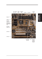
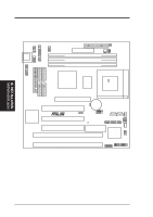
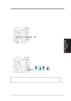
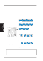
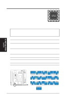
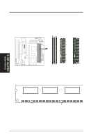
VIO0 VIO1 VIO0 VIO1 VIO0 VIO1 VIO0 VIO1 III. INST ALLATION Jumpers III. INSTALLATION Jumper Settings 1. Real Time Clock (RTC) RAM (CLRTC) The CMOS RAM is powered by the onboard button cell battery. To clear the RTC data: (1) Turn off your computer, (2) Short solder points using a small metalic object, (3) Turn on your computer, (4) Hold down during bootup and enter BIOS setup to re-enter user preferences. R P5A-B Clear RTC RAM CLRTC Short solder points to Clear CMOS 2. Voltage Input/Output Selection (VIO) This jumper allows you to select the voltage supplied to the DRAM, chipset, and AGP. R 1 2 3 3.5Volts 3.6Volts 3.8Volts (DEFAULT) 4.0Volts P5A-B Voltage Input/Output Selection WARNING! Using a higher voltage may help when overclocking but may result in the shortening of your computer components' life. Use default setting. ASUS P5A-B User's Manual 15
-
 1
1 -
2
-
3
-
4
-
5
-
6
-
7
-
8
-
9
-
 10
10 -
 11
11 -
 12
12 -
 13
13 -
 14
14 -
 15
15 -
 16
16 -
 17
17 -
 18
18 -
 19
19 -
 20
20 -
21
-
22
-
23
-
24
-
25
-
26
-
27
-
28
-
29
-
30
-
31
-
32
-
33
-
34
-
35
-
36
-
37
-
38
-
39
-
40
-
41
-
42
-
43
-
44
-
45
-
46
-
47
-
48
-
49
-
50
-
51
-
52
-
53
-
54
-
55
-
56
-
57
-
58
-
59
-
60
-
61
-
62
-
63
-
64
-
65
-
66
-
67
-
68
-
69
-
70
-
71
-
72
 |
 |
