Asus P5A-B P5A-B User Manual - Page 27
Chassis Intrusion Alarm Lead 4-1 pin CHASIS
 |
View all Asus P5A-B manuals
Add to My Manuals
Save this manual to your list of manuals |
Page 27 highlights
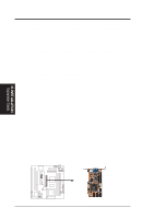
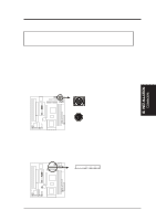
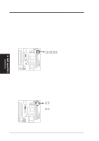
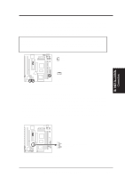
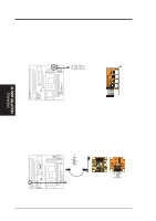
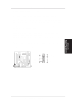
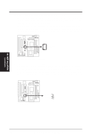
III. INSTALLATION 5. CPU Cooling Fan Connectors (FAN, 3 pins) This connector supports a 3-pin CPU cooling fan of 500mA (6W) or less with a minimum of 3,500RPM. Depending on the fan manufacturer, the wiring and plug may be different. The red wire should be Positive, the black should be Ground, and the yellow wire should be Rotation signal. WARNING! The CPU and/or motherboard will overheat if there is no airflow across the CPU. Damage may occur to the motherboard and/or the CPU fan if these pins are incorrectly used. These are not jumpers, do not place jumper caps over these pins. Power Supply Fan Ground +12 Volt Rotation Chassis Fan Power CPU Fan Power P5A-B Power Supply, CPU, Chassis Fan Power 6. Chassis Intrusion Alarm Lead (4-1 pin CHASIS) This lead is for a chassis intrusion monitor or sensor. The sensor is triggered when a high level signal is sent to the chassis signal lead. This occurs when a panel switch or light detector is triggered. This function requires the optional ASUS CIDB Chassis Sensor to be installed (see VI. ASUS CIDB). NOTE: When the chassis is opened, connect/short the Chassis Signal pin to the +5VSB pin. When the chassis is closed, connect/short the Chassis Signal pin to the Ground pin. Rotation +12 Volt Ground III. INST ALLATION Connectors R R +5Volt (Power Supply Stand By) Chassis Signal Ground P5A-B Chassis Open Alarm Lead ASUS P5A-B User's Manual 27
-
 1
1 -
2
-
3
-
4
-
5
-
6
-
7
-
8
-
9
-
10
-
11
-
12
-
13
-
14
-
15
-
16
-
17
-
18
-
19
-
20
-
21
-
 22
22 -
 23
23 -
 24
24 -
 25
25 -
 26
26 -
 27
27 -
 28
28 -
 29
29 -
 30
30 -
 31
31 -
 32
32 -
33
-
34
-
35
-
36
-
37
-
38
-
39
-
40
-
41
-
42
-
43
-
44
-
45
-
46
-
47
-
48
-
49
-
50
-
51
-
52
-
53
-
54
-
55
-
56
-
57
-
58
-
59
-
60
-
61
-
62
-
63
-
64
-
65
-
66
-
67
-
68
-
69
-
70
-
71
-
72
 |
 |
