Asus P5A-B P5A-B User Manual - Page 48
IDE 0 Master/Slave PIO/DMA Mode, IDE 1 Master/Slave PIO/DMA Mode Auto
 |
View all Asus P5A-B manuals
Add to My Manuals
Save this manual to your list of manuals |
Page 48 highlights
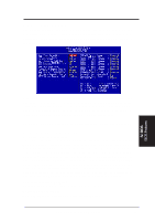
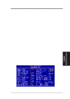
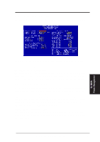
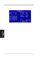
IV. BIOS Chipset Features IV. BIOS SOFTWARE Parallel Port Mode (ECP+EPP) This field allows you to set the operation mode of the parallel port. The setting Normal, allows normal-speed operation but in one direction only; EPP allows bidirectional parallel port operation at maximum speed; ECP allows the parallel port to operate in bidirectional mode and at a speed faster than the maximum data transfer rate; ECP+EPP allows normal speed operation in a two-way mode. ECP DMA Select (3) This selection is available only if you select ECP or ECP+EPP in the Parallel Port Mode. Select either DMA Channel 1, 3, or Disabled. Onboard IR (Disabled) When enabled, this field activates the onboard infrared feature and sets the second serial UART to support the infrared module connector on the motherboard. If your system already has a second serial port connected to the onboard COM2 connector, it will no longer work if you enable the infrared feature. By default, this field is set to Disabled, which leaves the second serial port UART to support the COM2 serial port connector. IR Mode (IrDA SIR) This motherboard supports IrDA compatible Serial Infrared (SIR) and Fast Infrared (FIR) communication modes. The FIR mode has two options: FIR/HP and FIR/ IBM, for computers or peripherals using HP and IBM's infrared transceivers, respectively. When using either FIR option, FIR DMA Select must be configured to reflect the DMA channel used by the port. FIR DMA Select (1) This allows you to configure the DMA channel used by the FIR port. Options are DMA 1 (default) or DMA 3. Onboard PCI IDE Enable (Both) You can select to enable the Primary IDE channel, Secondary IDE channel, Both, or Disable both channels (for systems with only SCSI drives). IDE Ultra DMA Mode (Auto) This sets the IDE UltraDMA to be active when using UltraDMA-capable IDE devices. The BIOS will automatically adjust or disable this setting for slower IDE devices so that Auto or high settings will not cause problems for older IDE devices. Choose Disable if you do not want this feature for all devices. IDE 0 Master/Slave PIO/DMA Mode, IDE 1 Master/Slave PIO/DMA Mode (Auto) Each channel (0 and 1) has both a master and a slave making four IDE devices possible. Because each IDE device may have a different Mode timing (0, 1, 2, 3, 4), it is necessary for these to be independent. PIO and DMA timings can be independently set. The default setting of Auto will allow autodetection to ensure optimal performance. IV. BIOS Chipset Features 48 ASUS P5A-B User's Manual
-
 1
1 -
2
-
3
-
4
-
5
-
6
-
7
-
8
-
9
-
10
-
11
-
12
-
13
-
14
-
15
-
16
-
17
-
18
-
19
-
20
-
21
-
22
-
23
-
24
-
25
-
26
-
27
-
28
-
29
-
30
-
31
-
32
-
33
-
34
-
35
-
36
-
37
-
38
-
39
-
40
-
41
-
42
-
 43
43 -
 44
44 -
 45
45 -
 46
46 -
 47
47 -
 48
48 -
 49
49 -
 50
50 -
 51
51 -
 52
52 -
 53
53 -
54
-
55
-
56
-
57
-
58
-
59
-
60
-
61
-
62
-
63
-
64
-
65
-
66
-
67
-
68
-
69
-
70
-
71
-
72
 |
 |
