Asus P5A-B P5A-B User Manual - Page 47
Onboard FDC Swap A & B No Swap
 |
View all Asus P5A-B manuals
Add to My Manuals
Save this manual to your list of manuals |
Page 47 highlights
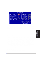
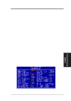
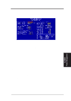
IV. BIOS Chipset Features IV. BIOS SOFTWARE Memory Hole At 15M-16M (Disabled) Enabling this feature reserves 15MB-16MB memory address space to ISA expansion cards that specifically require this setting. This makes the memory from 15MB and up unavailable to the system. Expansion cards can only access memory up to 16MB. The default is Disabled. Data Integrity Mode (Disabled) Data Integrity Mode or ECC is always Disabled when bus speeds ≥83MHz or when bus speed is equal to 75MHz and PCI clock is equal to the bus clock/2. When this field is Disabled, byte-wise write capability is available but no provision for protecting data integrity in the memory module array is available; although data errors are detected, they are not corrected. When Enabled, ECC is available, allowing a detection of single-bit and multiple-bit errors and recovery of single-bit errors. [See 2. System Memory (DIMM), section III for more information on memory modules.] KBD Clock Source Speed (8MHz) This field allows you to set the internal keyboard clock line speed. Set to either 12MHz or 16MHz if the default setting of 8MHz does not work with your operating system. Onboard FDC Controller (Enabled) When enabled, this field allows you to connect your floppy disk drives to the onboard floppy drive connector instead of a separate controller card. If you want to use a different controller card to connect the floppy disk drives, set this field to Disabled. Onboard FDC Swap A & B (No Swap) This field allows you to reverse the hardware drive letter assignments of your floppy disk drives. Two options are available: Swap AB and No Swap (default). If you want to switch drive letter assignments, set this field to Swap AB, and the swap will be controlled by the onboard chipset...Onboard Serial Port 1 (3F8H/IRQ4) Settings are 3F8H/IRQ4, 2F8H/IRQ3, 3E8H/IRQ4, 2E8H/IRQ10, and Disabled for the onboard serial connector. Onboard Serial Port 2 (2F8H/IRQ3) Settings are 3F8H/IRQ4, 2F8H/IRQ3, 3E8H/IRQ4, 2E8H/IRQ10, and Disabled for the onboard serial connector. Onboard Parallel Port (378H/IRQ7) This field sets the address of the onboard parallel port connector. You can select either 3BCH / IRQ 7, 378H / IRQ 7, 278H / IRQ 5, or Disabled. If you install an I/O card with a parallel port, ensure that there is no conflict in the address assignments. The PC can support up to three parallel ports as long as there are no conflicts for each port. IV. BIOS Chipset Features ASUS P5A-B User's Manual 47
-
 1
1 -
2
-
3
-
4
-
5
-
6
-
7
-
8
-
9
-
10
-
11
-
12
-
13
-
14
-
15
-
16
-
17
-
18
-
19
-
20
-
21
-
22
-
23
-
24
-
25
-
26
-
27
-
28
-
29
-
30
-
31
-
32
-
33
-
34
-
35
-
36
-
37
-
38
-
39
-
40
-
41
-
 42
42 -
 43
43 -
 44
44 -
 45
45 -
 46
46 -
 47
47 -
 48
48 -
 49
49 -
 50
50 -
 51
51 -
 52
52 -
53
-
54
-
55
-
56
-
57
-
58
-
59
-
60
-
61
-
62
-
63
-
64
-
65
-
66
-
67
-
68
-
69
-
70
-
71
-
72
 |
 |
