Asus P5A-B P5A-B User Manual - Page 33
ASUS P5A-B User's Manual, Audio Jack Connector 26-pin AUDIOCON, Digital Audio Interface 6-pin SPD0/
 |
View all Asus P5A-B manuals
Add to My Manuals
Save this manual to your list of manuals |
Page 33 highlights
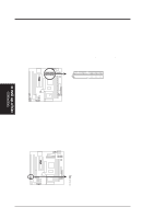
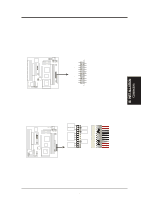
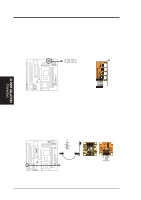
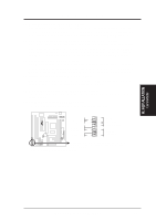
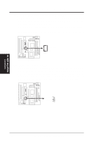
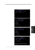
R R III. INSTALLATION 21. Audio Jack Connector (26-pin AUDIOCON) This connector is provided for audio input and output signals. Using a ribbon cable, you can connect this connector to a back panel audio connector. Audio connector 12 21 Red marking along edge Game/MIDI Port (15 pins) Line Output (1/8" phono) Microphone In (1/8" phono) Line Input (1/8" phono) 25 26 P5A-B Audio Jack Connector WARNING! Make sure that PIN 1 on the cable (use the red marking along the cable's edge as reference) is connected to PIN 1 on the audio connector module; otherwise, damage will occur. 22. Digital Audio Interface (6-pin SPD0/SPD1/TTL) This connector is the digital link between the motherboard and your devices, such as CD player, sampler, or DAT recorder. It allows the digital transmission of audio data in SPDIF (Sony/Philips Digital Interface) Format. P5A-B Digital Audio Interface TTL: Short this, if output device is TTL level SPDIFO: Digital Signal OUT SPDIFI: Digital Signal IN III. INST ALLATION Connectors ASUS P5A-B User's Manual 33
-
 1
1 -
2
-
3
-
4
-
5
-
6
-
7
-
8
-
9
-
10
-
11
-
12
-
13
-
14
-
15
-
16
-
17
-
18
-
19
-
20
-
21
-
22
-
23
-
24
-
25
-
26
-
27
-
 28
28 -
 29
29 -
 30
30 -
 31
31 -
 32
32 -
 33
33 -
 34
34 -
 35
35 -
 36
36 -
 37
37 -
 38
38 -
39
-
40
-
41
-
42
-
43
-
44
-
45
-
46
-
47
-
48
-
49
-
50
-
51
-
52
-
53
-
54
-
55
-
56
-
57
-
58
-
59
-
60
-
61
-
62
-
63
-
64
-
65
-
66
-
67
-
68
-
69
-
70
-
71
-
72
 |
 |
