Asus P5K3 Premium WiFi-AP User Manual - Page 52
CPU, chassis and power fan connectors, pin CPU_FAN, 3-pin CHA_FAN1-4, 3-pin PWR_FAN
 |
View all Asus P5K3 Premium WiFi-AP manuals
Add to My Manuals
Save this manual to your list of manuals |
Page 52 highlights
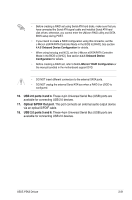
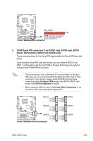
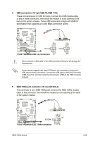
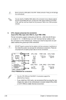
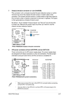
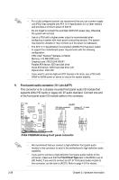
Never connect a USB cable to the IEEE 1394a connector. Doing so will damage the motherboard! You can attach a FireWire/1394 cable to this connector if your chassis suppots the front panel IEEE1394 port. Connect the 1394 cable to ASUS Q-Connector (1394, red) first, and then install the Q-Connector (1394) to the 1394 connector onboard. 6. CPU, chassis and power fan connectors (4-pin CPU_FAN, 3-pin CHA_FAN1-4, 3-pin PWR_FAN) The fan connectors support cooling fans of 350 mA ~ 2000 mA (24 W max.) or a total of 1 A ~ 7 A (84 W max.) at +12V. Connect the fan cables to the fan connectors on the motherboard, making sure that the black wire of each cable matches the ground pin of the connector. DO NOT forget to connect the fan cables to the fan connectors. Insufficient air flow inside the system may damage the motherboard components. These are not jumpers! Do not place jumper caps on the fan connectors! CPU_FAN PWR_FAN Rotation +12V GND CHA_FAN2 Rotation +12V GND GND CPU FAN PWR CPU FAN IN CPU FAN PWM ® P5K3 PREMIUM CHA_FAN1 GND +12V Rotation CHA_FAN3 CHA_FAN4 Rotation +12V GND GND +12V Rotation P5K3 PREMIUM Fan connectors • Only the CPU-FAN and CHA-FAN 1-4 connectors support the ASUS Q-Fan 2 feature. • If you install two VGA cards, we recommend that you plug the rear chassis fan cable to the motherboard connector labled CHA_FAN1 or CHA_FAN2 for better themal environment. 2-26 Chapter 2: Hardware information
-
 1
1 -
2
-
3
-
4
-
5
-
6
-
7
-
8
-
9
-
10
-
11
-
12
-
13
-
14
-
15
-
16
-
17
-
18
-
19
-
20
-
21
-
22
-
23
-
24
-
25
-
26
-
27
-
28
-
29
-
30
-
31
-
32
-
33
-
34
-
35
-
36
-
37
-
38
-
39
-
40
-
41
-
42
-
43
-
44
-
45
-
46
-
 47
47 -
 48
48 -
 49
49 -
 50
50 -
 51
51 -
 52
52 -
 53
53 -
 54
54 -
 55
55 -
 56
56 -
 57
57 -
58
-
59
-
60
-
61
-
62
-
63
-
64
-
65
-
66
-
67
-
68
-
69
-
70
-
71
-
72
-
73
-
74
-
75
-
76
-
77
-
78
-
79
-
80
-
81
-
82
-
83
-
84
-
85
-
86
-
87
-
88
-
89
-
90
-
91
-
92
-
93
-
94
-
95
-
96
-
97
-
98
-
99
-
100
-
101
-
102
-
103
-
104
-
105
-
106
-
107
-
108
-
109
-
110
-
111
-
112
-
113
-
114
-
115
-
116
-
117
-
118
-
119
-
120
-
121
-
122
-
123
-
124
-
125
-
126
-
127
-
128
-
129
-
130
-
131
-
132
-
133
-
134
-
135
-
136
-
137
-
138
-
139
-
140
-
141
-
142
-
143
-
144
-
145
-
146
-
147
-
148
-
149
-
150
-
151
-
152
-
153
-
154
-
155
-
156
-
157
-
158
-
159
-
160
-
161
-
162
-
163
-
164
-
165
-
166
-
167
-
168
-
169
-
170
-
171
-
172
 |
 |