Asus P5KPL SE User Manual - Page 21
System memory
 |
View all Asus P5KPL SE manuals
Add to My Manuals
Save this manual to your list of manuals |
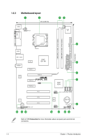
Page 21 highlights
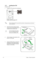
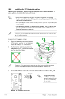
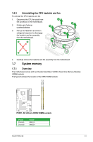
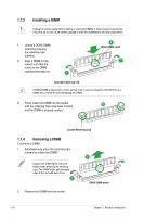
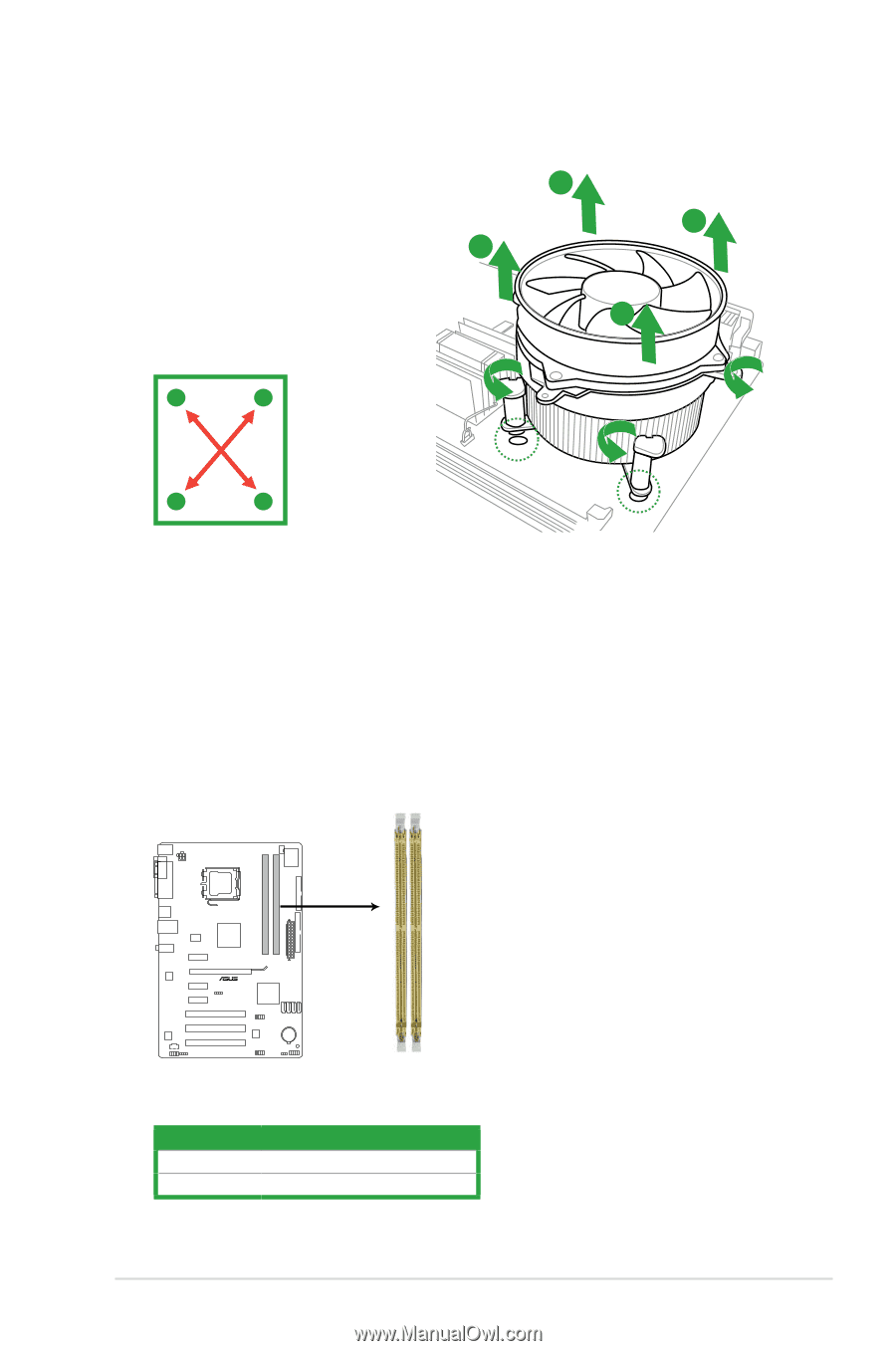
1.6.3 Uninstalling the CPU heatsink and fan To uninstall the CPU heatsink and fan 1. Disconnect the CPU fan cable from A the connector on the motherboard. B 2. Rotate each fastener counterclockwise. B 3. Pull up two fasteners at a time in a diagonal sequence to disengage A the heatsink and fan assembly from the motherboard. A B B A 4. Carefully remove the heatsink and fan assembly from the motherboard. 1.7 System memory 1.7.1 Overview The motherboard comes with two Double Data Rate 2 (DDR2) Dual Inline Memory Modules (DIMM) sockets. The figure illustrates the location of the DDR2 DIMM sockets: DIMM_A1 DIMM_B1 P5KPL SE P5KPL SE 240-pin DDR2 DIMM sockets Channel Channel A Channel B Sockets DIMM_A1 DIMM_B1 ASUS P5KPL SE 1-11
-
 1
1 -
2
-
3
-
4
-
5
-
6
-
7
-
8
-
9
-
10
-
11
-
12
-
13
-
14
-
15
-
 16
16 -
 17
17 -
 18
18 -
 19
19 -
 20
20 -
 21
21 -
 22
22 -
 23
23 -
 24
24 -
 25
25 -
 26
26 -
27
-
28
-
29
-
30
-
31
-
32
-
33
-
34
-
35
-
36
-
37
-
38
-
39
-
40
-
41
-
42
-
43
-
44
-
45
-
46
-
47
-
48
-
49
-
50
-
51
-
52
-
53
-
54
-
55
-
56
-
57
-
58
-
59
-
60
 |
 |
ASUS P5KPL SE
1-11
1.6.3
Uninstalling the CPU heatsink and fan
To uninstall the CPU heatsink and fan
1.
Disconnect the CPU fan cable from
the connector on the motherboard.
2.
Rotate each fastener
counterclockwise.
3.
Pull up two fasteners at a time in
a diagonal sequence to disengage
the heatsink and fan assembly
from the motherboard.
4.
Carefully remove the heatsink and fan assembly from the motherboard.
1.7
System memory
1.7.1
Overview
The motherboard comes with two Double Data Rate 2 (DDR2) Dual Inline Memory Modules
(DIMM) sockets.
The figure illustrates the location of the DDR2 DIMM sockets:
Channel
Sockets
Channel A
DIMM_A1
Channel B
DIMM_B1
A
A
B
B
A
A
B
B
P5KPL SE
P5KPL SE 240-pin DDR2 DIMM sockets
DIMM_A
1
DIMM_B
1