Asus P5P800 SE P5P800 SE User's Manual for English Edition
Asus P5P800 SE Manual
 |
View all Asus P5P800 SE manuals
Add to My Manuals
Save this manual to your list of manuals |
Asus P5P800 SE manual content summary:
- Asus P5P800 SE | P5P800 SE User's Manual for English Edition - Page 1
P5P800 SE Motherboard - Asus P5P800 SE | P5P800 SE User's Manual for English Edition - Page 2
express written permission of ASUSTeK COMPUTER INC. ("ASUS"). Product warranty or service will not be extended if: (1) the ASUS HAS BEEN ADVISED OF THE POSSIBILITY OF SUCH DAMAGES ARISING FROM ANY DEFECT OR ERROR IN THIS MANUAL OR PRODUCT. SPECIFICATIONS AND INFORMATION CONTAINED IN THIS MANUAL - Asus P5P800 SE | P5P800 SE User's Manual for English Edition - Page 3
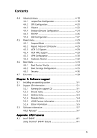
x P5P800 SE specifications summary xi Chapter 1: Product introduction 1.1 Welcome 1-1 1.2 Package contents 1-1 1.3 Special features 1-2 1.3.1 Product highlights 1-2 1.3.2 Innovative ASUS features 1-4 Chapter 2: Hardware information 2.1 Before you proceed 2-1 2.2 Motherboard overview - Asus P5P800 SE | P5P800 SE User's Manual for English Edition - Page 4
utility 4-3 4.1.4 ASUS CrashFree BIOS 2 utility 4-5 4.1.5 ASUS Update utility 4-7 4.2 BIOS setup program 4-10 4.2.1 BIOS menu screen 4-11 4.2.2 Menu bar 4-11 4.2.3 Navigation keys 4-11 4.2.4 Menu items 4-12 4.2.5 Sub-menu items 4-12 4.2.6 Configuration fields 4-12 4.2.7 Pop-up window 4-12 - Asus P5P800 SE | P5P800 SE User's Manual for English Edition - Page 5
CD information 5-1 5.2.1 Running the support CD 5-1 5.2.2 Drivers menu 5-2 5.2.3 Utilities menu 5-3 5.2.4 Manuals menu 5-4 5.2.5 ASUS Contact information 5-4 5.2.6 Other information 5-5 5.3 Software information 5-7 ASUS MyLogo 5-7 Appendix: CPU features A.1 Intel® EM64T A-1 Using the - Asus P5P800 SE | P5P800 SE User's Manual for English Edition - Page 6
Contents A.2 Enhanced Intel SpeedStep® Technology (EIST A-1 A.2.1 System requirements A-1 A.2.2 Using the EIST A-2 A.3 Intel® Hyper-Threading Technology A-3 Using the Hyper-Threading Technology A-3 vi - Asus P5P800 SE | P5P800 SE User's Manual for English Edition - Page 7
. This equipment generates, uses and can radiate radio frequency energy and, if not installed and used in accordance with manufacturer's instructions, may cause harmful interference to radio communications. However, there is no guarantee that interference will not occur in a particular installation - Asus P5P800 SE | P5P800 SE User's Manual for English Edition - Page 8
supply is broken, do not try to fix it by yourself. Contact a qualified service technician or your retailer. Operation safety • Before installing the motherboard and adding devices on it, carefully read all the manuals that came with the package. • Before using the product, make sure all cables - Asus P5P800 SE | P5P800 SE User's Manual for English Edition - Page 9
This chapter describes the CPU features that the motherboard supports. Where to find more information Refer to the following sources for additional information and for product and software updates. 1. ASUS websites The ASUS website provides updated information on ASUS hardware and software products - Asus P5P800 SE | P5P800 SE User's Manual for English Edition - Page 10
following symbols used throughout this manual. D A N G E R / W A R N I N G : Information to prevent injury to yourself when trying to complete a task. C A U T I O N : Information to prevent damage to the components when trying to complete a task. I M P O R T A N T : Instructions that you MUST follow - Asus P5P800 SE | P5P800 SE User's Manual for English Edition - Page 11
P5P800 SE specifications summary CPU Chipset Front Side Bus Memory Expansion slots Storage AI Audio LAN Overclocking USB Special features BIOS features LGA775 socket for Intel® Pentium® 4/Celeron processor Intel® Pentium® D ready Compatible with the Intel® PCG 05A/O5B and 04A/04B processors - Asus P5P800 SE | P5P800 SE User's Manual for English Edition - Page 12
P5P800 SE specifications summary Rear panel Internal connectors Power Requirement Form Factor Support CD contents 1 x Parallel port 1 x Serial port 1 x LAN (RJ-45) port 4 x USB 2.0 ports 1 x S/PDIF out port 1 x PS/2 keyboard port 1 x PS/2 mouse port 6-channel audio ports 1 x Floppy disk drive - Asus P5P800 SE | P5P800 SE User's Manual for English Edition - Page 13
This chapter describes the motherboard features and the new technologies it supports. 1Product introduction - Asus P5P800 SE | P5P800 SE User's Manual for English Edition - Page 14
Chapter summary 1.1 Welcome 1-1 1.2 Package contents 1-1 1.3 Special features 1-2 ASUS P5P800 SE - Asus P5P800 SE | P5P800 SE User's Manual for English Edition - Page 15
the list below. 1.2 Package contents Check your motherboard package for the following items. Motherboard ASUS P5P800 SE motherboard D s ASUS motherboard support CD D o c u m e n t a t i o n User guide If any of the above items is damaged or missing, contact your retailer. ASUS P5P800 SE 1-1 - Asus P5P800 SE | P5P800 SE User's Manual for English Edition - Page 16
CPU support The motherboard supports dual-core processors containing two physical CPU cores with dedicated L2 caches to meet demands for more powerful processing. See page 2-6 for details. ASUS Hyper-Path Technology This unique technology from ASUS optimizes the true potential of the Intel - Asus P5P800 SE | P5P800 SE User's Manual for English Edition - Page 17
6-channel audio support The motherboard comes with the ADI AD1888 SoundMAX audio CODEC that lets you enjoy high-quality 6-channel audio without having to buy advanced sound cards. The ADI SoundMAX Digital Audio System features state-of-the-art DLS2 MIDI synthesizer with Yamaha DLS by XG sound set, - Asus P5P800 SE | P5P800 SE User's Manual for English Edition - Page 18
See pages 4-35 and 5-7 for details. C.P.R. (CPU Parameter Recall) The C.P.R. feature of the motherboard BIOS allows automatic re-setting to the BIOS default settings in case the system hangs due to overclocking. When the system hangs due to overclocking, C.P.R. eliminates the need to open the system - Asus P5P800 SE | P5P800 SE User's Manual for English Edition - Page 19
This chapter lists the hardware setup procedures that you have to perform when installing system components. It includes description of the jumpers and connectors on the motherboard. 2 Hardware information - Asus P5P800 SE | P5P800 SE User's Manual for English Edition - Page 20
Chapter summary 2.1 Before you proceed 2-1 2.2 Motherboard overview 2-2 2.3 Central Processing Unit (CPU 2-6 2.4 System memory 2-13 2.5 Expansion slots 2-17 2.6 Jumpers 2-20 2.7 Connectors 2-23 ASUS P5P800 SE - Asus P5P800 SE | P5P800 SE User's Manual for English Edition - Page 21
is a reminder that you should shut down the system and unplug the power cable before removing or plugging in any motherboard component. The illustration below shows the location of the onboard LED. ® P5P800 SE P5P800 SE Onboard LED SB_PWR ON Standby Power OFF Powered Off ASUS P5P800 SE 2-1 - Asus P5P800 SE | P5P800 SE User's Manual for English Edition - Page 22
image below. 2.2.2 Screw holes Place six (6) screws into the holes indicated by circles to secure the motherboard to the chassis. Do not overtighten the screws! Doing so can damage the motherboard. Place this side towards the rear of the chassis ® P5P800 SE 2-2 Chapter 2: Hardware information - Asus P5P800 SE | P5P800 SE User's Manual for English Edition - Page 23
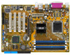
) DDR DIMM_B2 (64 bit,184-pin module) SEC_IDE 30.5cm (12.0in) 2.2.3 Motherboard layout 21.3cm (8.4in) PS/2KBMS KBPWR T: Mouse B: Keyboard ATX12V SPDIF_O LGA775 PARALLEL Accelerated Graphics Port (AGP) PCI1 ® PCI2 PCI3 P5P800 SE PCI4 4Mbit Firmware Hub GAME FLOPPY USBPW78 USBPW56 CR2032 - Asus P5P800 SE | P5P800 SE User's Manual for English Edition - Page 24
2.2.4 Layout Contents Slots 1. DDR DIMM slots 2. PCI slots 3. AGP slot Page 2-13 2-19 2-19 Jumpers 1. Clear RTC RAM (3-pin CLRTC) 2. USB Device wake-up (3-pin USBPW12, USBPW34, USBPW56, USBPW78) 3. Keyboard power (3-pin KBPWR) Page 2-20 2-21 2-22 Rear panel connectors 1. PS/2 mouse port 2. - Asus P5P800 SE | P5P800 SE User's Manual for English Edition - Page 25
ATA connectors (7-pin SATA1, SATA2) 4. CPU fan connector (4-pin CPU_FAN) 5. Chassis fan connector (3-pin CHA_FAN) 6. Power fan connector (3-pin PWR_FAN) 7. Digital audio connector (4-1 pin SPDIF_OUT) 8. USB headers 2-28 2-28 2-28 2-28 2-29 2-30 2-30 2-31 2-31 2-31 2-32 2-32 2-33 ASUS P5P800 SE 2-5 - Asus P5P800 SE | P5P800 SE User's Manual for English Edition - Page 26
/incorrect removal of the PnP cap. • This motherboard does not support Intel® Pentium® 4 Processor Extreme Edition. 2.3.1 Installling the CPU To install a CPU: 1. Locate the CPU socket on the motherboard. ® P5P800 SE P5P800 SE Socket 775 Before installing the CPU, make sure that the socket box is - Asus P5P800 SE | P5P800 SE User's Manual for English Edition - Page 27
cap B from the load plate window to remove (B). Load plate 5. Position the CPU over the socket, making sure that the gold triangle is on the bottom-left corner of the socket. The socket alignment key should fit A l i g n m e n t k e y into the CPU notch. Gold triangle mark ASUS P5P800 SE A 2-7 - Asus P5P800 SE | P5P800 SE User's Manual for English Edition - Page 28
into the socket to prevent bending the connectors on the socket and damaging the CPU! The motherboard supports Intel® Pentium® 4 LGA775 processors with the Intel® Enhanced Memory 64 Technology (EM64T), Enhanced Intel SpeedStep® Technology (EIST), and Hyper-Threading Technology. Refer to the Appendix - Asus P5P800 SE | P5P800 SE User's Manual for English Edition - Page 29
. To install the CPU heatsink and fan: 1. Place the heatsink on top of the installed CPU, making sure that the four fasteners match the holes on the motherboard. Fastener Motherboard hole Make sure each fastener is oriented as shown, with the narrow groove directed outward. ASUS P5P800 SE 2-9 - Asus P5P800 SE | P5P800 SE User's Manual for English Edition - Page 30
fan and heatsink assembly is in place, connect the CPU fan cable to the connector on the motherboard labeled CPU_FAN. ® P5P800 SE CPU_FAN GND CPU FAN PWR CPU FAN IN CPU FAN PWM P5P800 SE CPU fan connector Do not forget to connect the CPU fan connector! Hardware monitoring errors can occur if you - Asus P5P800 SE | P5P800 SE User's Manual for English Edition - Page 31
and fan: 1. Disconnect the CPU fan cable from the connector on the motherboard. 2. Rotate each fastener counterclockwise. 3. Pull up two fasteners at a time in a diagonal sequence to disengage the heatsink B and fan assembly from the A A motherboard. B A B B A ASUS P5P800 SE 2-11 - Asus P5P800 SE | P5P800 SE User's Manual for English Edition - Page 32
4. Remove the heatsink and fan assembly from the motherboard. 5. Rotate each fastener clockwise to reset the orientation. When reset, each fastener should be oriented as shown, with the narrow groove directed outward. 2-12 Chapter 2: Hardware information - Asus P5P800 SE | P5P800 SE User's Manual for English Edition - Page 33
you obtain memory modules from the same vendor. See the DDR400 Qualified Vendor List (QVL) on page 2-15. 2. Make sure that the memory frequency matches the CPU FSB (Front Side Bus). Refer to the M e m o r y f r e q u e n c y / modules are not supported in this motherboard. ASUS P5P800 SE 2-13 - Asus P5P800 SE | P5P800 SE User's Manual for English Edition - Page 34
) and another same size pair in DIMM_A2 and DIMM_B2 (black sockets) Memory frequency/CPU FSB synchronization This motherboard supports different memory frequencies depending on the CPU FSB (Front Side Bus) and the type of DDR DIMM. CPU FSB 800 MHz 533 MHz DDR DIMM Type PC3200/PC2700/PC2100 PC2700 - Asus P5P800 SE | P5P800 SE User's Manual for English Edition - Page 35
Qualified Vendors List Size supports on pair of modules inserted into either the yellow slots or the black slots as one pair of Dual-channel memory configuration. C - support for 4 modules inserted into the yellow and black slots as two pairs of Dual-channel memory configuration. ASUS P5P800 SE - Asus P5P800 SE | P5P800 SE User's Manual for English Edition - Page 36
components. Failure to do so may cause severe damage to both the motherboard and the components. 1. Unlock a DIMM socket by pressing the retaining clips retaining clips outward to unlock the DIMM. 1 1 DDR DIMM notch Support the DIMM lightly with your fingers when pressing the retaining clips. The - Asus P5P800 SE | P5P800 SE User's Manual for English Edition - Page 37
it by adjusting the software settings. 1. Turn on the system and change the necessary BIOS settings, if any. See Chapter 4 for information on BIOS setup. 2. Assign an IRQ to the card. Refer to the tables on the next page. 3. Install the software drivers for the expansion card. ASUS P5P800 SE 2-17 - Asus P5P800 SE | P5P800 SE User's Manual for English Edition - Page 38
for this motherboard PCI slot LAN Onboard Audio A B -- -- -- -- shared - -- shared - -- -- shared - -- -- C used - - - - D used - - - E F G H - - - used shared - - - shared - - - shared shared shared - --- When using PCI cards on shared slots, ensure that the drivers support - Asus P5P800 SE | P5P800 SE User's Manual for English Edition - Page 39
+1.5V specification. Note the notches on the card golden fingers to ensure that they fit the AGP slot on your motherboard. Install only 1.5 V or 0.8 V AGP cards on this motherboard! 3.3V AGP cards are not supported in this motherboard. ® P5P800 SE Keyed for 1.5v P5P800 SE Accelerated Graphics - Asus P5P800 SE | P5P800 SE User's Manual for English Edition - Page 40
! ® P5P800 SE P5P800 SE Clear RTC RAM CLRTC 12 23 Normal (Default) Clear CMOS You do not need to clear the RTC when the system hangs due to overclocking. For system failure due to overclocking, use the C.P.R. (CPU Parameter Recall) feature. Shut down and reboot the system so the BIOS can - Asus P5P800 SE | P5P800 SE User's Manual for English Edition - Page 41
CPU, DRAM in slow refresh, power supply in reduced power mode). The USBPWR12 and USBPWR34 jumpers are for the rear USB ports. The USBPWR56 and USBPWR78 jumper is for the internal USB connectors that you can connect to additional USB ports. P5P800 SE P5P800 SE or in sleep mode. ASUS P5P800 SE 2-21 - Asus P5P800 SE | P5P800 SE User's Manual for English Edition - Page 42
the Space Bar). This feature requires an ATX power supply that can supply at least 1A on the +5VSB lead, and a corresponding setting in the BIOS. KBPWR 12 23 +5V (Default) +5VSB ® P5P800 SE P5P800 SE Keyboard power setting 2-22 Chapter 2: Hardware information - Asus P5P800 SE | P5P800 SE User's Manual for English Edition - Page 43
a Local Area Network (LAN) through a network hub. Refer to the table below for the LAN port LED indications. LAN port LED indications a microphone. Refer to the audio configuration table on the next page for the function of the audio ports in 2, 4, or 6-channel configuration. ASUS P5P800 SE 2-23 - Asus P5P800 SE | P5P800 SE User's Manual for English Edition - Page 44
. S e r i a l p o r t. This 9-pin serial port is for serial devices. 1 0 . C o a x i a l S / P D I F O u t p o r t . This port connects an external audio output device via a coaxial S/PDIF cable. 1 1 . P S / 2 k e y b o a r d p o r t ( p u r p l e ) . This port is for a PS/2 keyboard. 2-24 Chapter - Asus P5P800 SE | P5P800 SE User's Manual for English Edition - Page 45
PIN 1. P5P800 SE PIN 1 P5P800 SE Floppy disk drive connector 2 . IDE connectors (40-1 pin PRI_IDE, SEC_IDE) These connectors are for Ultra DMA 100/66 signal cables. The Ultra DMA 100/66 signal cable has three connectors: a blue connector for the primary IDE connector on the motherboard, a black - Asus P5P800 SE | P5P800 SE User's Manual for English Edition - Page 46
GND ® P5P800 SE SATA1 P5P800 SE SATA connectors GND RSATA_TXP1 RSATA_TXN1 GND RSATA_RXP1 RSATA_RXN1 GND Important notes on Serial ATA • Install the Windows® 2000 Service Pack 4 or the Windows® XP Service Pack1 or later versions before using the Serial ATA feature. • Hot plug support for Serial - Asus P5P800 SE | P5P800 SE User's Manual for English Edition - Page 47
the related BIOS items. BIOS Item Onboard IDE Operate Mode Enhanced Mode Support On IDE Port Settings Windows 2000/XP Enhanced Mode S-ATA - Windows 98/ME A B C Compatible Mode Compatible Mode Compatible Mode - - - Primary P-ATA+S-ATA Sec. P-ATA+S-ATA P-ATA Ports Only ASUS P5P800 SE 2-27 - Asus P5P800 SE | P5P800 SE User's Manual for English Edition - Page 48
may damage the motherboard components. These are not jumpers! DO NOT place jumper caps on the fan connectors! ® P5P800 SE CPU_FAN GND CPU FAN PWR CPU FAN IN CPU FAN PWM PWR_FAN CHA_FAN Rotation +12V GND Rotation +12V GND P5P800 SE Fan connectors 5 . Digital audio connector (4-1 pin SPDIF_OUT - Asus P5P800 SE | P5P800 SE User's Manual for English Edition - Page 49
the back of the system chassis. These USB connectors comply with USB 2.0 specification that supports up to 480 Mbps connection speed. USB+5V USB_P8USB_P8+ GND NC USB+5V USB_P6USB_P6+ GND NC ® P5P800 SE USB56 1 P5P800 SE USB 2.0 connectors USB78 1 USB+5V USB_P7USB_P7+ GND USB+5V USB_P5USB_P5 - Asus P5P800 SE | P5P800 SE User's Manual for English Edition - Page 50
a Power Supply Unit (PSU) with a higher power rating if you intend to install additional devices. ATX12V +12V DC GND ® P5P800 SE +12V DC GND P5P800 SE ATX power connector EATXPWR +3 Volts -12 Volts Ground PSON# Ground Ground Ground -5 Volts +5 Volts +5 Volts +5 Volts Ground +3 Volts +3 Volts - Asus P5P800 SE | P5P800 SE User's Manual for English Edition - Page 51
pin CD, AUX) These connectors allow you to receive stereo audio input from sound sources such as a CD-ROM, TV tuner, or MPEG card. ® P5P800 SE Right Audio Channel Ground Ground Left Audio Channel CD(Black) AUX(White) P5P800 SE Internal audio connectors 9 . GAME/MIDI port connector (16-1 pin GAME - Asus P5P800 SE | P5P800 SE User's Manual for English Edition - Page 52
LINE_OUT_L/BLINE_OUT_L are shorted with jumper caps. Remove the caps only when you are connecting the front panel audio cable. FP_AUDIO ® P5P800 SE P5P800 SE Front panel audio connector AGND +5VA BLINE_OUT_R BLINE_OUT_L MIC2 MICPWR Line out_R NC Line out_L 2-32 Chapter 2: Hardware information - Asus P5P800 SE | P5P800 SE User's Manual for English Edition - Page 53
on the BIOS settings. Pressing the power switch for more than four seconds while the system is ON turns the system OFF. • Reset button (Blue 2-pin RESET) This 2-pin connector is for the chassis-mounted reset button for system reboot without turning off the system power. ASUS P5P800 SE 2-33 - Asus P5P800 SE | P5P800 SE User's Manual for English Edition - Page 54
2-34 Chapter 2: Hardware information - Asus P5P800 SE | P5P800 SE User's Manual for English Edition - Page 55
This chapter describes the power up Powerin3g up sequence, the vocal POST messages, and ways of shutting down the system. - Asus P5P800 SE | P5P800 SE User's Manual for English Edition - Page 56
Chapter summary 3.1 Starting up for the first time 3-1 3.2 Powering off the computer 3-2 ASUS P5P800 SE - Asus P5P800 SE | P5P800 SE User's Manual for English Edition - Page 57
then runs the power-on self tests or POST. While the tests are running, the BIOS beeps (see BIOS beep codes table below) or additional messages appear on the screen. If you do not see on, hold down the key to enter the BIOS Setup. Follow the instructions in Chapter 4. ASUS P5P800 SE 3-1 - Asus P5P800 SE | P5P800 SE User's Manual for English Edition - Page 58
to shut down the computer. 3. The power supply should turn off after Windows® shuts down. If you are using Windows® XP: 1. Click the S t a r t button then select T u BIOS setting. Pressing the power switch for more than four seconds lets the system enter the soft-off mode regardless of the BIOS - Asus P5P800 SE | P5P800 SE User's Manual for English Edition - Page 59
This chapter tells how to change the system settings through the BIOS Setup menus. Detailed descriptions of the BIOS parameters are also provided. 4 BIOS setup - Asus P5P800 SE | P5P800 SE User's Manual for English Edition - Page 60
Chapter summary 4.1 Managing and updating your BIOS 4-1 4.2 BIOS setup program 4-10 4.3 Main menu 4-13 4.4 Advanced menu 4-18 4.5 Power menu 4-29 4.6 Boot menu 4-34 4.7 Exit menu 4-39 ASUS P5P800 SE - Asus P5P800 SE | P5P800 SE User's Manual for English Edition - Page 61
motherboard BIOS using the ASUS Update or AFUDOS utilities. 4.1.1 Creating a bootable floppy disk 1. Do either one of the following to create a bootable floppy disk. DOS environment a. Insert a 1.44MB floppy disk into the drive. b. At the DOS prompt, type format A:/S then press . Windows® XP - Asus P5P800 SE | P5P800 SE User's Manual for English Edition - Page 62
the ASUS website (www.asus.com) to download the latest BIOS file for the motherboard and rename the same to P 5 P 8 0 0 S E . R O M. 2. Save the BIOS file to a floppy disk, then restart the system. 3. Press + during POST to display the following. EZFlash starting BIOS update Checking - Asus P5P800 SE | P5P800 SE User's Manual for English Edition - Page 63
afudos /oOLDBIOS1.ROM AMI Firmware Update Utility - Version 1.19(ASUS V2.07(03.11.24BB)) Copyright (C) 2003 American Megatrends, Inc. All rights reserved. Reading flash ..... done Write to file ...ok A:\> The utility returns to the DOS prompt after copying the current BIOS file. ASUS P5P800SE 4-3 - Asus P5P800 SE | P5P800 SE User's Manual for English Edition - Page 64
Updating the BIOS file To update the BIOS file using the AFUDOS utility: 1. Visit the ASUS website (www.asus.com) and download the latest BIOS file for the motherboard. Save the BIOS file to a bootable floppy disk. Write the BIOS filename on a piece of paper. You need to type the exact BIOS filename - Asus P5P800 SE | P5P800 SE User's Manual for English Edition - Page 65
done Please restart your computer A:\> 4.1.4 ASUS CrashFree BIOS 2 utility The ASUS CrashFree BIOS 2 is an auto recovery tool that allows you to restore the BIOS file when it fails or gets corrupted during the updating process. You can update a corrupted BIOS file using the motherboard support CD - Asus P5P800 SE | P5P800 SE User's Manual for English Edition - Page 66
updating the BIOS! Doing so can cause system boot failure! 4. Restart the system after the utility completes the updating process. The recovered BIOS may not be the latest BIOS version for this motherboard. Visit the ASUS website (www.asus.com) to download the latest BIOS file. 4-6 Chapter 4: BIOS - Asus P5P800 SE | P5P800 SE User's Manual for English Edition - Page 67
the BIOS version information. This utility is available in the support CD that comes with the motherboard package. ASUS Update requires an Internet connection either through a network or an Internet Service Provider (ISP). Installing ASUS Update To install ASUS Update: 1. Place the support CD in - Asus P5P800 SE | P5P800 SE User's Manual for English Edition - Page 68
t e. The ASUS Update main window appears. 2. Select U p d a t e B I O S f r o m 3. Select the ASUS FTP site t h e I n t e r n e t option from the nearest you to avoid network drop-down menu, then click traffic, or click A u t o S e l e c t. N e x t. Click N e x t. 4-8 Chapter 4: BIOS setup - Asus P5P800 SE | P5P800 SE User's Manual for English Edition - Page 69
a t e. The ASUS Update main window appears. 2. Select U p d a t e B I O S f r o m a f i l e option from the drop-down menu, then click N e x t. 3. Locate the BIOS file from the O p e n window, then click O p e n. 4. Follow the screen instructions to complete the update process. ASUS P5P800SE 4-9 - Asus P5P800 SE | P5P800 SE User's Manual for English Edition - Page 70
program This motherboard supports a programmable firmware chip that you can update using the provided utility described in section "4.1 Managing and updating your BIOS." Use the BIOS Setup program when you are installing a motherboard, reconfiguring your system, or prompted to "Run Setup". This - Asus P5P800 SE | P5P800 SE User's Manual for English Edition - Page 71
4.2.1 BIOS menu screen Menu items Menu bar Configuration fields General help System Time System Date Legacy Diskette A Language Primary IDE Master Primary keys to select items in the menu and change the settings. Some of the navigation keys differ from one screen to another. ASUS P5P800 SE 4-11 - Asus P5P800 SE | P5P800 SE User's Manual for English Edition - Page 72
displays the specific items [1.44M, 3.5 in] [English] :[ST320413A] :[ASUS CD-S340] :[Not Detected] :[Not Detected] :[ list of options. Refer to "4.2.7 Pop-up window." 4.2.7 Pop-up window Select a menu item then press to display a pop-up window window Scroll bar 4-12 Chapter 4: BIOS setup - Asus P5P800 SE | P5P800 SE User's Manual for English Edition - Page 73
overview of the basic system information. Refer to section "4.2.1 BIOS menu screen" for information on the menu screen items 3.5 in.] 4.3.4 Language [English] Allows you to choose the BIOS language version from the options. Configuration options: [Français] [German] [English] ASUS P5P800 SE 4-13 - Asus P5P800 SE | P5P800 SE User's Manual for English Edition - Page 74
Supported Type LBA/Large Mode Block(Multi-sector Transfer) PIO Mode DMA Mode Smart Monitoring 32Bit Data Transfer [Auto] [Auto] [Auto] [Auto] [Auto] [Auto] [Disabled] The BIOS appropriate IDE device type. Select CDROM if you are specifically configuring a CD-ROM drive. Select ARMD (ATAPI Removable - Asus P5P800 SE | P5P800 SE User's Manual for English Edition - Page 75
> if you wish to configure the item. IDE Configuration Onboard IDE Operate Mode Enhanced Mode Support On IDE Detect Time Out (Sec) [Enhanced Mode] [S-ATA] [35] Onboard IDE are using native OS, such as Windows® 2000/XP. Configuration options: [Compatible Mode] [Enhanced Mode] ASUS P5P800 SE 4-15 - Asus P5P800 SE | P5P800 SE User's Manual for English Edition - Page 76
advanced users only. If you set to any of these options and encounter problems, revert to the default setting S - A T A. Configuration options: [P- [P-ATA Ports Only] disables the two Serial ATA ports supported by ICH5. Configuration options: [Primary P-ATA+S-ATA] ] [35] 4-16 Chapter 4: BIOS setup - Asus P5P800 SE | P5P800 SE User's Manual for English Edition - Page 77
04/07/04 Processor Type Speed Count : Genuine Intel(R) CPU 3.20GHz : 2800 MHz : 1 System Memory Size : 512MB AMI BIOS Displays the auto-detected BIOS information Processor Displays the auto-detected CPU specification System Memory Displays the auto-detected system memory ASUS P5P800 SE 4-17 - Asus P5P800 SE | P5P800 SE User's Manual for English Edition - Page 78
of the preset overclocking options. Configuration options: [Manual] [Standard] [Overclock 5%] [Overclock 10%] [Overclock 20%] [Overclock 30%] CPU Ratio [ 14] Sets the ratio between the CPU Core Clock and the Front Side Bus frequency. The default value of this item is auto-detected by BIOS. Use the - Asus P5P800 SE | P5P800 SE User's Manual for English Edition - Page 79
] [72.73/36.36] [80.00/40.00] CPU VCore Voltage [Auto] Allows selection of the CPU VCore voltage. The configuration options depend on the CPU installed. Selecting a very high VCore voltage may cause the system to become unstable! If this happens, revert to the default setting. ASUS P5P800 SE 4-19 - Asus P5P800 SE | P5P800 SE User's Manual for English Edition - Page 80
and Exit ESC Exit F1 General Help F10 Save and Exit ESC Exit CPU Ratio [ 14] Sets the ratio between the CPU Core Clock and the Front Side Bus frequency. The default value of this item is auto-detected by BIOS. Use the or keys to adjust the values. This item appears only when - Asus P5P800 SE | P5P800 SE User's Manual for English Edition - Page 81
following item appears only when you installed an Intel® Pentium® 4 CPU that supports the Enhanced Intel SpeedStep™ Technology (EIST). Intel(R) SpeedStep Technology [Automatic details on how to use the EIST feature. • The motherboard comes with a BIOS files that supports EIST. ASUS P5P800 SE 4-21 - Asus P5P800 SE | P5P800 SE User's Manual for English Edition - Page 82
are set according to the DRAM SPD (Serial Presence Detect). When disabled, you can manually set the DRAM timing parameters through the DRAM sub-items. The following sub-items appear [8 Clocks] Sets the DRAM Burst Length. Configuration options: [4 Clocks] [8 Clocks] 4-22 Chapter 4: BIOS setup - Asus P5P800 SE | P5P800 SE User's Manual for English Edition - Page 83
when [Enabled] minimize latencies from CPU to memory to boost system performance. Enable this item to activate the ASUS HyperPath Technology feature. Configuration options: Revision [1.1] Sets the Multi-Processor Specification (MPS) version. Configuration options: [1.1] [1.4] ASUS P5P800 SE 4-23 - Asus P5P800 SE | P5P800 SE User's Manual for English Edition - Page 84
[Auto] [Auto] allows the BIOS to detect whether you are using any audio device. If an audio device is detected, the onboard audio controller is enabled; if no audio device is detected, the controller is disabled. Configuration options: [Disabled] [Auto] OnBoard LAN [Enabled] Allows you to enable - Asus P5P800 SE | P5P800 SE User's Manual for English Edition - Page 85
. This item appears only when the O n b o a r d G a m e / M I D I P o r t item is set to 200/300, 200/330, 208/300, or 208/330. Configuration options: [IRQ5] [IRQ9] [IRQ10] [IRQ11] ASUS P5P800 SE 4-25 - Asus P5P800 SE | P5P800 SE User's Manual for English Edition - Page 86
IRQ Preference [Auto] [Auto] [Auto] [Auto] +- Change Option F1 General Help F10 Save and Exit ESC Exit Plug And Play O/S [No] When set to [No], BIOS configures all the devices in the system. When set to [Yes] and if you install a Plug and Play operating system, the operating system configures the - Asus P5P800 SE | P5P800 SE User's Manual for English Edition - Page 87
BIOS to use PCI bus mastering when reading/writing to IDE devices. Configuration options: [Disabled] [Enabled] IRQ-xx assigned to [PCI Device] When set to [PCI Device], the specific Devices Enabled: None USB Function Legacy USB Support USB 2.0 Controller USB 2.0 Controller Mode ASUS P5P800 SE 4-27 - Asus P5P800 SE | P5P800 SE User's Manual for English Edition - Page 88
detected, the USB controller legacy mode is enabled. If no USB device is detected, the legacy USB support is disabled. Configuration options: [Disabled] [Enabled] [Auto] USB 2.0 Controller [Enabled] Allows you Type items appear only when there are installed USB devices. 4-28 Chapter 4: BIOS setup - Asus P5P800 SE | P5P800 SE User's Manual for English Edition - Page 89
you to enable or disable the Advanced Configuration and Power Interface (ACPI) support in the Application-Specific Integrated Circuit (ASIC). When set to Enabled, the ACPI APIC table pointer is included in the RSDT pointer list. Configuration options: [Disabled] [Enabled] ASUS P5P800 SE 4-29 - Asus P5P800 SE | P5P800 SE User's Manual for English Edition - Page 90
: [00] ~ [59] RTC Alarm Second [xx] Sets the RTC Alarm Second. Use the and keys to adjust the value. Configuration options: [00] ~ [59] 4-30 Chapter 4: BIOS setup - Asus P5P800 SE | P5P800 SE User's Manual for English Edition - Page 91
], this parameter allows you to turn on the system through a PCI LAN or modem card. This feature requires an ATX power supply that provides at Enabled] Power On By PS/2 Keyboard [Disabled] Allows you to use specific keys on the keyboard to turn on the system. This feature requires ASUS P5P800 SE 4-31 - Asus P5P800 SE | P5P800 SE User's Manual for English Edition - Page 92
hardware monitor automatically detects and displays the motherboard, power supply unit and CPU temperatures. Select Ignored if you do not wish to display the detected temperatures. CPU Q-Fan Control [Disabled] Allows you to enable or disable the ASUS Q-Fan feature that smartly adjusts the fan - Asus P5P800 SE | P5P800 SE User's Manual for English Edition - Page 93
fan speeds in rotations per minute (RPM). If the fan is not connected to the motherboard, the field shows N/A. VCORE Voltage, 3.3V Voltage, 5V Voltage, 12V Voltage The onboard hardware monitor automatically detects the voltage output through the onboard voltage regulators. ASUS P5P800 SE 4-33 - Asus P5P800 SE | P5P800 SE User's Manual for English Edition - Page 94
Priority 1st Boot Device 2nd Boot Device 3rd Boot Device [1st FLOPPY DRIVE] [PM-ST330620A] [PS-ASUS CD-S360] 1st ~ xxth Boot Device [1st Floppy Drive] These items specify the boot device priority sequence in the system. Configuration options: [xxxxx Drive] [Disabled] 4-34 Chapter 4: BIOS setup - Asus P5P800 SE | P5P800 SE User's Manual for English Edition - Page 95
Support [Auto] Allows you to enable or disable support for PS/2 mouse. Configuration options: [Disabled] [Enabled] [Auto] Wait for 'F1' If Error [Enabled] When set to Enabled, the system waits for the F1 key to be pressed when error occurs. Configuration options: [Disabled] [Enabled] ASUS P5P800 SE - Asus P5P800 SE | P5P800 SE User's Manual for English Edition - Page 96
as in setting a user password. To clear the supervisor password, select the Change Supervisor Password then press . The message "Password Uninstalled" appears. 4-36 Chapter 4: BIOS setup - Asus P5P800 SE | P5P800 SE User's Manual for English Edition - Page 97
If you forget your BIOS password, you can clear clear it by erasing the CMOS Real Time Clock (RTC) RAM. See section "2.6 Jumpers" for information on how to erase the RTC RAM. After you have set a letters and/or numbers, then press . 3. Confirm the password when prompted. ASUS P5P800 SE 4-37 - Asus P5P800 SE | P5P800 SE User's Manual for English Edition - Page 98
Select this item to clear the user password. Password Check [Setup] When set to [Setup], BIOS checks for user password when accessing the Setup utility. When set to [Always], BIOS checks for user password both when accessing Setup and booting the system. Configuration options: [Setup] [Always - Asus P5P800 SE | P5P800 SE User's Manual for English Edition - Page 99
other than System Date, System Time, and Password, the BIOS asks for a confirmation before exiting. Discard Changes This window appears. Select Y e s to load default values. Select E x i t & S a v e C h a n g e s or make other changes before saving the values to the non-volatile RAM. ASUS P5P800 SE - Asus P5P800 SE | P5P800 SE User's Manual for English Edition - Page 100
4-40 Chapter 4: BIOS setup - Asus P5P800 SE | P5P800 SE User's Manual for English Edition - Page 101
This chapter describes the contents of the support CD that comes with the motherboard package. 5 Software support - Asus P5P800 SE | P5P800 SE User's Manual for English Edition - Page 102
Chapter summary 5.1 Installing an operating system 5-1 5.2 Support CD information 5-1 5.3 Software information 5-7 ASUS P5P800 SE - Asus P5P800 SE | P5P800 SE User's Manual for English Edition - Page 103
that you install Windows® 2000 Service Pack 4 or the Windows® XP Service Pack2 or later versions before installing the drivers for better compatibility and system stability. 5.2 Support CD information The support CD that came with the motherboard package contains the drivers, software applications - Asus P5P800 SE | P5P800 SE User's Manual for English Edition - Page 104
activate the devices. Intel Chipset Inf Update Program This item installs the Intel® Chipset INF Update Program. This driver enables Plug-n-Play INF support for the Intel® chipset components on the motherboard. When installed to the target system, this driver provides the method for configuring the - Asus P5P800 SE | P5P800 SE User's Manual for English Edition - Page 105
motherboard supports. ASUS PC Probe This smart utility monitors the fan speed, CPU temperature, and system voltages, and alerts you of any detected problems. This utility helps you keep your computer in healthy operating condition. ASUS Update Allows you to download the latest version of the BIOS - Asus P5P800 SE | P5P800 SE User's Manual for English Edition - Page 106
manual file. SoundMAX User Guide Allows you to open the AD1888 SoundMAX user guide. 5.2.5 ASUS Contact information Click the C o n t a c t tab to display the ASUS contact information. You can also find this information on the inside front cover of this user guide. 5-4 Chapter 5: Software support - Asus P5P800 SE | P5P800 SE User's Manual for English Edition - Page 107
give additional information on the motherboard and the contents of the support CD. Click an icon to display the specified information. Motherboard Info Displays the general specifications of the motherboard. Browse this CD Displays the support CD contents in graphical format. ASUS P5P800 SE 5-5 - Asus P5P800 SE | P5P800 SE User's Manual for English Edition - Page 108
Technical support Form Displays the ASUS Technical Support Request Form that you have to fill out when requesting technical support. Filelist Displays the contents of the support CD and a brief description of each in text format. 5-6 Chapter 5: Software support - Asus P5P800 SE | P5P800 SE User's Manual for English Edition - Page 109
e B I O S f r o m a f i l e from the drop down menu, then click N e x t. 5. When prompted, locate the new BIOS file, then click N e x t. The ASUS MyLogo™ window appears. 6. From the left window pane, select the folder that contains the image you intend to use as your boot logo. ASUS P5P800 SE 5-7 - Asus P5P800 SE | P5P800 SE User's Manual for English Edition - Page 110
right window pane, select an image to enlarge by clicking on it. 8. Adjust the boot image to your desired size by selecting a value on the R a t i o box. 9. When the screen returns to the ASUS Update utility, flash the original BIOS to load the new boot logo. 10. After flashing the BIOS, restart the - Asus P5P800 SE | P5P800 SE User's Manual for English Edition - Page 111
CPU featAures The Appendix describes the CPU features that the motherboard supports. - Asus P5P800 SE | P5P800 SE User's Manual for English Edition - Page 112
Chapter summary A A.1 Intel® EM64T A-1 A.2 Enhanced Intel SpeedStep® Technology (EIST A-1 A.3 Intel® Hyper-Threading Technology A-3 ASUS P5P800 SE - Asus P5P800 SE | P5P800 SE User's Manual for English Edition - Page 113
requirements Before using EIST, check your system if it meets the following requirements: • Intel® Pentium® 4 processor with EIST support • BIOS file with EIST support • Operating system with EIST support (Windows® XP SP2/Windows® Server 2003 SP1/Linux 2.6 kernel or later versions) ASUS P5P800 SE - Asus P5P800 SE | P5P800 SE User's Manual for English Edition - Page 114
BIOS setup. 5. After the computer restarts, right click on a blank space on the desktop, then select Properties from the pop-up menu. 6. When the Display Properties window Properties window. After you adjust the power scheme, the CPU internal frequency slightly decreases when the CPU loading is - Asus P5P800 SE | P5P800 SE User's Manual for English Edition - Page 115
system and enter the BIOS Setup. Under the A d v a n c e d M e n u, make sure that the item H y p e r - T h r e a d i n g T e c h n o l o g y is set to E n a b l e d. The BIOS item appears only if you installed a CPU that supports Hyper-Threading Technology. 3. Restart the computer. ASUS P5P800 SE - Asus P5P800 SE | P5P800 SE User's Manual for English Edition - Page 116
A-4 Appendix: CPU features
-
 1
1 -
 2
2 -
 3
3 -
 4
4 -
 5
5 -
 6
6 -
 7
7 -
8
-
9
-
10
-
11
-
12
-
13
-
14
-
15
-
16
-
17
-
18
-
19
-
20
-
21
-
22
-
23
-
24
-
25
-
26
-
27
-
28
-
29
-
30
-
31
-
32
-
33
-
34
-
35
-
36
-
37
-
38
-
39
-
40
-
41
-
42
-
43
-
44
-
45
-
46
-
47
-
48
-
49
-
50
-
51
-
52
-
53
-
54
-
55
-
56
-
57
-
58
-
59
-
60
-
61
-
62
-
63
-
64
-
65
-
66
-
67
-
68
-
69
-
70
-
71
-
72
-
73
-
74
-
75
-
76
-
77
-
78
-
79
-
80
-
81
-
82
-
83
-
84
-
85
-
86
-
87
-
88
-
89
-
90
-
91
-
92
-
93
-
94
-
95
-
96
-
97
-
98
-
99
-
100
-
101
-
102
-
103
-
104
-
105
-
106
-
107
-
108
-
109
-
110
-
111
-
112
-
113
-
114
-
115
-
116
 |
 |

Motherboard
P5P800 SE