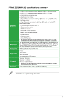
Asus PRIME Z270M-PLUS PRIME Z270M-PLUS Users manual ENGLISH - Page 12
Layout contents, ATX power connectors 24-pin EATXPWR, 8-pin EATX12V - ddr4
 |
View all Asus PRIME Z270M-PLUS manuals
Add to My Manuals
Save this manual to your list of manuals |
Page 12 highlights
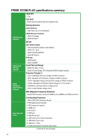
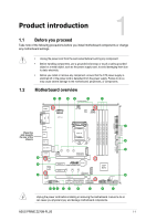
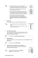
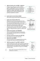
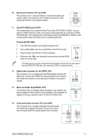
1.2.1 Layout contents Connectors/Jumpers/Slots/LED 1. CPU and chassis fan connectors (4-pin CPU_FAN, 4-pin CHA_FAN1/2) 2. ATX power connectors (24-pin EATXPWR, 8-pin EATX12V) 3. M.2 Socket3 4. Intel® LGA1151 CPU socket 5. DDR4 DIMM slots 6. Intel® Z270 Serial ATA 6.0Gb/s ports (SATA6G_1~4) 7. USB 3.0 connectors (20-1 pin USB3_12, USB3_34) 8. System panel connector (20-5 pin PANEL) 9. USB 2.0 connectors (10-1 pin USB1112, USB1314) 10. Serial Port Connector (10-1 pin COM) 11. Clear RTC RAM (2-pin CLRTC) 12. Digital audio connector (4-1 pin SPDIF_OUT) 13. Mono out header (2-pin MONO_OUT) 14 Front panel audio connector (10-1 pin AAFP) 15 PCI Express 3.0/2.0 x16 slots 16 PCI Express 3.0/2.0 x1 slots Page 1-2 1-2 1-3 1-3 1-3 1-3 1-4 1-4 1-4 1-5 1-5 1-5 1-5 1-5 1-6 1-6 1. CPU and chassis fan connectors (4-pin CPU_FAN, 4-pin CHA_FAN1/2) Connect the fan cables to the fan connectors on the motherboard, ensuring that the black wire of each cable matches the ground pin of the connector. Do not forget to connect the fan cables to the fan connectors. Insufficient air flow inside the system may damage the motherboard components. These are not jumpers! Do not place jumper caps on the fan connectors! The CPU_FAN connector supports a CPU fan of maximum 1A (12 W) fan power. CPU_FAN CHA_FAN CPU FAN PWM CPU FAN IN CPU FAN PWR GND CHA FAN PWM CHA FAN IN CHA FAN PWR GND 2. ATX power connectors (24-pin EATXPWR, 8-pin EATX12V) These connectors are for ATX power supply plugs. The power supply plugs are designed to fit these connectors in only one orientation. Find the proper orientation and push down firmly until the connectors completely fit. 1-2 Chapter 1: Product introduction
-
 1
1 -
2
-
3
-
4
-
5
-
6
-
 7
7 -
 8
8 -
 9
9 -
 10
10 -
 11
11 -
 12
12 -
 13
13 -
 14
14 -
 15
15 -
 16
16 -
 17
17 -
18
-
19
-
20
-
21
-
22
-
23
-
24
-
25
-
26
-
27
-
28
-
29
-
30
-
31
-
32
-
33
-
34
-
35
-
36
-
37
-
38
-
39
-
40
-
41
-
42
-
43
-
44
-
45
-
46
-
47
-
48
-
49
-
50
-
51
-
52
-
53
-
54
-
55
-
56
-
57
-
58
-
59
-
60
-
61
-
62
-
63
-
64
-
65
-
66
-
67
-
68
-
69
-
70
-
71
-
72
-
73
-
74
-
75
-
76
-
77
-
78
-
79
-
80
 |
 |