Asus Pro E500 G6 User Manual - Page 49
Layout contents, Connectors/Jumpers/Buttons and switches/Slots
 |
View all Asus Pro E500 G6 manuals
Add to My Manuals
Save this manual to your list of manuals |
Page 49 highlights
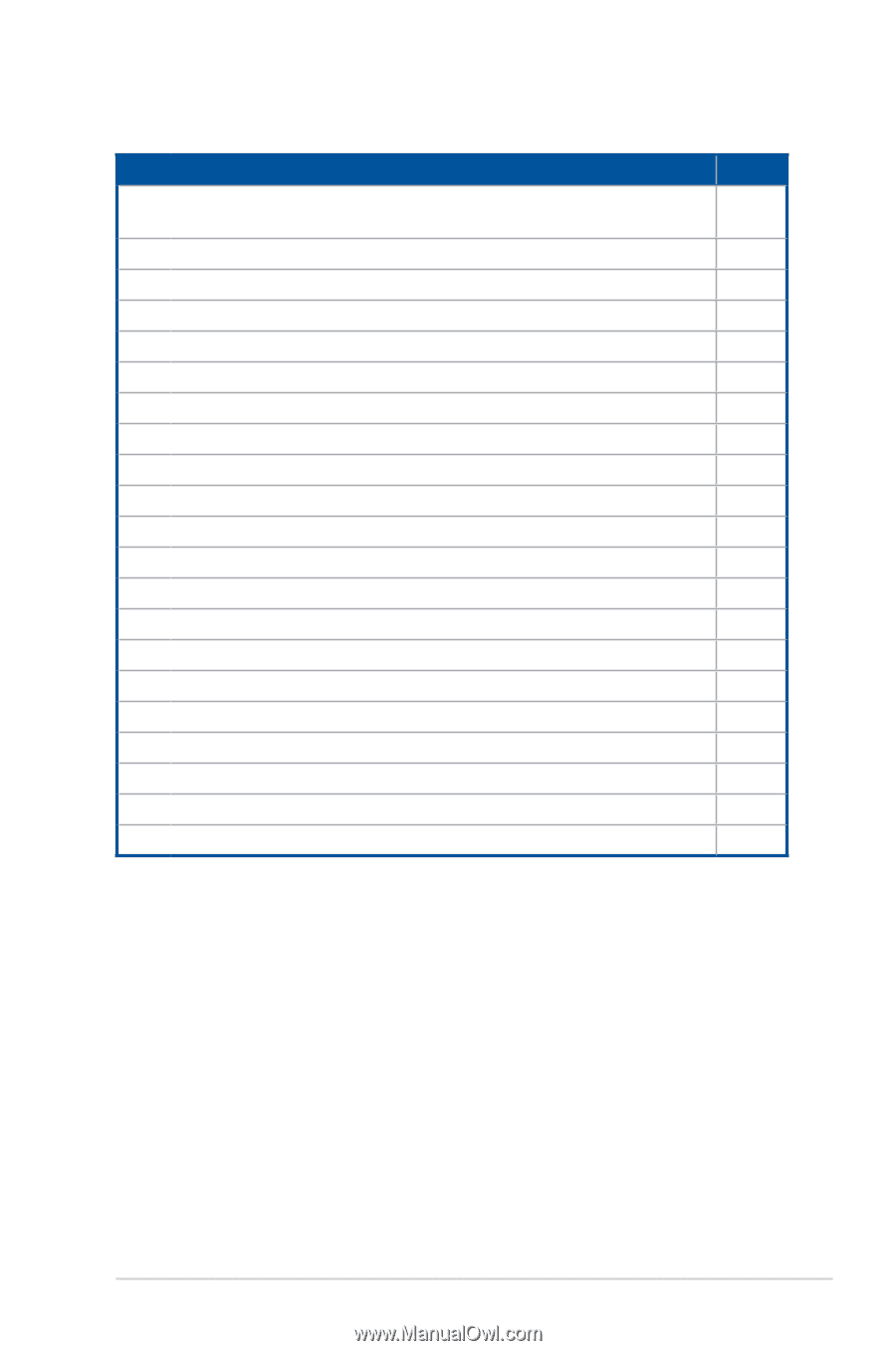
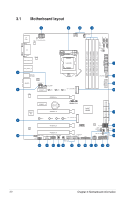
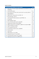
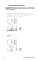
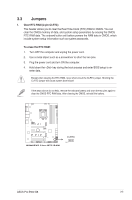
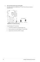
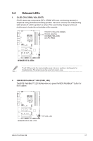
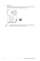
Layout contents Connectors/Jumpers/Buttons and switches/Slots 1. ATX power connectors (24-pin EATXPWR; 8-pin EATX12V; 6-pin EATX12V_1) 2. LGA1200 CPU socket 3. Fan connectors (4-pin CPU_FAN; 4-pin CPU_OPT; 4-pin CHA_FAN1-3) 4. DDR4 DIMM slots 5. USB 3.2 Gen 1 connector (20-1 pin U32G1_12) 6. M.2 sockets (M.2_1; M.2_2) 7. Intel® Serial ATA 6 Gb/s connectors (7-pin SATA6G_1-8) 8. Q-Code LED 9. BIOS FlashBack™ button 10. LPT and Q-Code switch (3-pin LPT_P80_SW) 11. System panel connector (20-3 pin PANEL) 12. USB 2.0 connectors (10-1 pin USB1112, USB1314; 4-pin Type-A USB9) 13. Clear RTC RAM (2-pin CLRTC) 14. LPT connector (26-1 pin LPT) 15. Thermal Sensor connector (2-pin T_SENSOR) 16. Power-on button 17. Reset button 18. TPM connector (14-1 pin TPM) 19. Serial port connector (10-1 pin COM1) 20. Front panel audio connector (10-1 pin AAFP) 21. Digital audio connector (4-1 pin SPDIF_OUT) Page 3-15 2-4 3-13 2-7 3-11 3-16 3-9 3-8 2-23 3-6 3-14 3-12 3-5 3-17 3-17 3-4 3-4 3-10 3-12 3-10 3-13 ASUS Pro E500 G6 3-3
-
 1
1 -
2
-
3
-
4
-
5
-
6
-
7
-
8
-
9
-
10
-
11
-
12
-
13
-
14
-
15
-
16
-
17
-
18
-
19
-
20
-
21
-
22
-
23
-
24
-
25
-
26
-
27
-
28
-
29
-
30
-
31
-
32
-
33
-
34
-
35
-
36
-
37
-
38
-
39
-
40
-
41
-
42
-
43
-
 44
44 -
 45
45 -
 46
46 -
 47
47 -
 48
48 -
 49
49 -
 50
50 -
 51
51 -
 52
52 -
 53
53 -
 54
54 -
55
-
56
-
57
-
58
-
59
-
60
-
61
-
62
-
63
-
64
-
65
-
66
-
67
-
68
-
69
-
70
-
71
-
72
-
73
-
74
-
75
-
76
-
77
-
78
-
79
-
80
-
81
-
82
-
83
-
84
-
85
-
86
-
87
-
88
-
89
-
90
-
91
-
92
-
93
-
94
-
95
-
96
-
97
-
98
-
99
-
100
-
101
-
102
-
103
-
104
-
105
-
106
-
107
-
108
-
109
-
110
-
111
-
112
-
113
-
114
-
115
-
116
-
117
-
118
-
119
-
120
-
121
-
122
-
123
-
124
-
125
-
126
-
127
-
128
-
129
-
130
-
131
-
132
-
133
-
134
-
135
-
136
-
137
-
138
-
139
-
140
-
141
-
142
-
143
-
144
-
145
-
146
-
147
-
148
-
149
-
150
-
151
-
152
 |
 |