Asus ROG Crosshair VIII Formula Users Manual English - Page 19
Layout contents, ROG CROSSHAIR VIII FORMULA
 |
View all Asus ROG Crosshair VIII Formula manuals
Add to My Manuals
Save this manual to your list of manuals |
Page 19 highlights
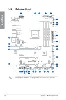
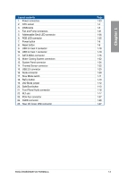
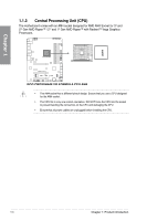
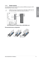
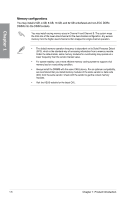
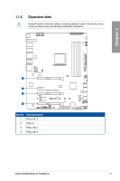
Chapter 1 Layout contents 1. Power connectors 2. CPU socket 3. DIMM slots 4. Fan and Pump connectors 5. Addressable Gen2 LED connector 6. RGB LED connector 7. Power button 8. Reset button 9. USB 3.2 Gen 2 connector 10. USB 3.2 Gen 1 connector 11. SATA 6Gb/s connector 12. Water Cooling System connectors 13. System Panel connector 14. Thermal Sensor connector 15. USB 2.0 connector 16. Node connector 17. Slow Mode switch 18. ReTry button 19. LN2 Mode jumper 20. Safe Boot button 21. Front Panel Audio connector 22. M.2 slot 23. PCH Fan connector 24. OLED connector 25. Rear I/O Cover LED connector Page 1-23 1-4 1-5 1-21 1-26 1-25 1-9 1-9 1-18 1-19 1-16 1-22 1-24 1-22 1-20 1-28 1-11 1-10 1-12 1-10 1-18 1-17 1-27 1-28 1-27 ROG CROSSHAIR VIII FORMULA 1-3
-
 1
1 -
2
-
3
-
4
-
5
-
6
-
7
-
8
-
9
-
10
-
11
-
12
-
13
-
 14
14 -
 15
15 -
 16
16 -
 17
17 -
 18
18 -
 19
19 -
 20
20 -
 21
21 -
 22
22 -
 23
23 -
 24
24 -
25
-
26
-
27
-
28
-
29
-
30
-
31
-
32
-
33
-
34
-
35
-
36
-
37
-
38
-
39
-
40
-
41
-
42
-
43
-
44
-
45
-
46
-
47
-
48
-
49
-
50
-
51
-
52
-
53
-
54
-
55
-
56
-
57
-
58
-
59
-
60
-
61
-
62
-
63
-
64
-
65
-
66
-
67
-
68
-
69
-
70
-
71
-
72
-
73
-
74
-
75
-
76
-
77
-
78
-
79
-
80
-
81
-
82
-
83
-
84
-
85
-
86
-
87
-
88
-
89
-
90
-
91
-
92
-
93
-
94
-
95
-
96
-
97
-
98
-
99
-
100
-
101
-
102
-
103
-
104
-
105
-
106
 |
 |