Asus ROG MAXIMUS Z790 HERO BTF Users Manual English - Page 18
Layout contents, Product Introduction
 |
View all Asus ROG MAXIMUS Z790 HERO BTF manuals
Add to My Manuals
Save this manual to your list of manuals |
Page 18 highlights
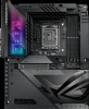
Chapter 1 Layout contents 1. CPU socket 2. DIMM slots 3. Expansion slots 4. Fan and Pump headers 5. Power connectors 6. GC_HPWR Power connectors 7. M.2 slot 8. SATA 6Gb/s port 9. USB 20Gbps Type-C® Front Panel connector 10. USB 5Gbps header 11. USB 2.0 header 12. Addressable Gen 2 header 13. Aura RGB header 14. FlexKey button 15. Front Panel Audio header 16. Start button 17. System Panel header 18. Installation LED switch 19. Thermal Sensor header 20. Q-Code LED 21. Q-LEDs 22. GC_HPWR Power Plug LEDs 23. Storage Device Activity LED 24. 8-pin CPU Power Plug LED Page 1-6 1-6 1-7 1-9 1-10 1-10 1-11 1-11 1-12 1-12 1-12 1-13 1-13 1-14 1-14 1-14 1-15 1-15 1-16 1-16 1-16 1-17 1-17 1-17 1-4 Chapter 1: Product Introduction
-
 1
1 -
2
-
3
-
4
-
5
-
6
-
7
-
8
-
9
-
10
-
11
-
12
-
 13
13 -
 14
14 -
 15
15 -
 16
16 -
 17
17 -
 18
18 -
 19
19 -
 20
20 -
 21
21 -
 22
22 -
 23
23 -
24
-
25
-
26
-
27
-
28
-
29
-
30
-
31
-
32
-
33
-
34
-
35
-
36
-
37
-
38
-
39
-
40
-
41
-
42
-
43
-
44
-
45
-
46
-
47
-
48
-
49
-
50
-
51
-
52
-
53
-
54
-
55
-
56
-
57
-
58
-
59
-
60
-
61
-
62
-
63
-
64
-
65
-
66
-
67
-
68
-
69
-
70
-
71
-
72
-
73
-
74
 |
 |

1-4
Chapter 1: Product Introduction
Chapter 1
Layout contents
Page
1.
CPU socket
1-6
2.
DIMM slots
1-6
3.
Expansion slots
1-7
4.
Fan and Pump headers
1-9
5.
Power connectors
1-10
6.
GC_HPWR Power connectors
1-10
7.
M.2 slot
1-11
8.
SATA 6Gb/s port
1-11
9.
USB 20Gbps Type-C
®
Front Panel connector
1-12
10.
USB 5Gbps header
1-12
11.
USB 2.0 header
1-12
12.
Addressable Gen 2 header
1-13
13.
Aura RGB header
1-13
14.
FlexKey button
1-14
15.
Front Panel Audio header
1-14
16.
Start button
1-14
17.
System Panel header
1-15
18.
Installation LED switch
1-15
19.
Thermal Sensor header
1-16
20.
Q-Code LED
1-16
21.
Q-LEDs
1-16
22.
GC_HPWR Power Plug LEDs
1-17
23.
Storage Device Activity LED
1-17
24.
8-pin CPU Power Plug LED
1-17