Asus ROG Rampage VI Extreme Encore Users Manual English - Page 24
Recommended VGA configuration
 |
View all Asus ROG Rampage VI Extreme Encore manuals
Add to My Manuals
Save this manual to your list of manuals |
Page 24 highlights
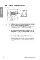
Chapter 1 Recommended VGA configuration 48-LANE CPU Slot Description 1. PCIe 3.0/2.0 X16_1 2. PCIe 3.0/2.0 X4 (PCH) 3. PCIe 3.0/2.0 X16_2 4. PCIe 3.0/2.0 X16_3 5. M.2_1 (PCH) 6. M.2_2 (PCH) 7. DIMM.2_1 8. DIMM.2_2 Single VGA Dual VGA Triple VGA x16 x16 x16 x16 x16 Shares bandwidth with M.2_2 - x16 x16 x16 x8 - - x4 x8 x8 V V V V V Shares bandwidth with PCIE 3.0/2.0 X4 V V V V V V V V - V 44-LANE CPU Slot Description 1. PCIe 3.0/2.0 X16_1 2. PCIe 3.0/2.0 X4 (PCH) 3. PCIe 3.0/2.0 X16_2 4. PCIe 3.0/2.0 X16_3 5. M.2_1 (PCH) 6. M.2_2 (PCH) 7. DIMM.2_1 8. DIMM.2_2 Single VGA Dual VGA Triple VGA x16 x16 x16 x16 x16 Shares bandwidth with M.2_2 - x8 x16 x8 x16 - - - x4 x4 V V V V V Shares bandwidth with PCIe 3.0/2.0 X4 V V V V V V V - V - 28-LANE CPU Slot Description 1. PCIe 3.0/2.0 X16_1 2. PCIe 3.0/2.0 X4 (PCH) 3. PCIe 3.0/2.0 X16_2 4. PCIe 3.0/2.0 X16_3 5. M.2_1 (PCH) 6. M.2_2 (PCH) 7. DIMM.2_1 8. DIMM.2_2 Single VGA Dual VGA Triple VGA x16 x16 x16 Shares bandwidth with M.2_2 - x8 x8 - - x4 V V V Shares bandwidth with PCIe 3.0/2.0 X4 - - - - - - • We recommend that you provide sufficient power when running CrossFireX™ or SLI® mode. • Ensure to connect both the 8-pin power plugs when running CrossFireX™ or SLI® mode. • Connect a chassis fan to the chassis fan connectors when using multiple graphics cards for better thermal environment. 1-8 Chapter 1: Product Introduction
-
 1
1 -
2
-
3
-
4
-
5
-
6
-
7
-
8
-
9
-
10
-
11
-
12
-
13
-
14
-
15
-
16
-
17
-
18
-
 19
19 -
 20
20 -
 21
21 -
 22
22 -
 23
23 -
 24
24 -
 25
25 -
 26
26 -
 27
27 -
 28
28 -
 29
29 -
30
-
31
-
32
-
33
-
34
-
35
-
36
-
37
-
38
-
39
-
40
-
41
-
42
-
43
-
44
-
45
-
46
-
47
-
48
-
49
-
50
-
51
-
52
-
53
-
54
-
55
-
56
-
57
-
58
-
59
-
60
-
61
-
62
-
63
-
64
-
65
-
66
-
67
-
68
-
69
-
70
-
71
-
72
-
73
-
74
-
75
-
76
-
77
-
78
-
79
-
80
-
81
-
82
-
83
-
84
-
85
-
86
-
87
-
88
-
89
-
90
-
91
-
92
-
93
-
94
-
95
-
96
-
97
-
98
-
99
-
100
-
101
-
102
-
103
-
104
-
105
-
106
-
107
-
108
-
109
-
110
-
111
-
112
-
113
-
114
-
115
-
116
 |
 |
