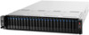
Asus RS720-E7-RS24-EG RS720-E7-RS24-EG User's Manual - Page 28
Hardware setup, plate G., Position the CPU over the socket
 |
View all Asus RS720-E7-RS24-EG manuals
Add to My Manuals
Save this manual to your list of manuals |
Page 28 highlights
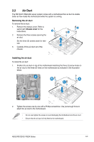
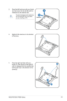
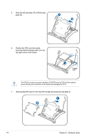
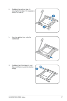
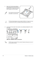
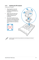
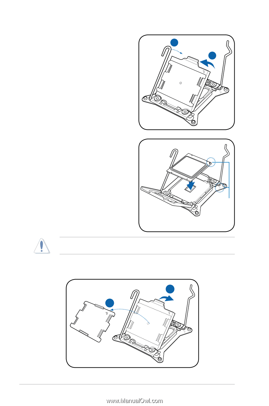
5. Push the left load lever (F) to lift the load plate (G). F G 6. Position the CPU over the socket, ensuring that the triangle mark is on the top‑right corner of the socket. Triangle mark The CPU fits in only one correct orientation. DO NOT force the CPU into the socket to prevent bending the connectors on the socket and damaging the CPU! 7. Remove the PnP cap (H) from the CPU socket and close the load plate (I). I H 2-6 Chapter 2: Hardware setup
-
 1
1 -
2
-
3
-
4
-
5
-
6
-
7
-
8
-
9
-
10
-
11
-
12
-
13
-
14
-
15
-
16
-
17
-
18
-
19
-
20
-
21
-
22
-
 23
23 -
 24
24 -
 25
25 -
 26
26 -
 27
27 -
 28
28 -
 29
29 -
 30
30 -
 31
31 -
 32
32 -
 33
33 -
34
-
35
-
36
-
37
-
38
-
39
-
40
-
41
-
42
-
43
-
44
-
45
-
46
-
47
-
48
-
49
-
50
-
51
-
52
-
53
-
54
-
55
-
56
-
57
-
58
-
59
-
60
-
61
-
62
-
63
-
64
-
65
-
66
-
67
-
68
-
69
-
70
-
71
-
72
-
73
-
74
-
75
-
76
-
77
-
78
-
79
-
80
-
81
-
82
-
83
-
84
-
85
-
86
-
87
-
88
-
89
-
90
-
91
-
92
-
93
-
94
-
95
-
96
-
97
-
98
-
99
-
100
-
101
-
102
-
103
-
104
-
105
-
106
-
107
-
108
-
109
-
110
-
111
-
112
-
113
-
114
-
115
-
116
-
117
-
118
-
119
-
120
-
121
-
122
-
123
-
124
-
125
-
126
-
127
-
128
-
129
-
130
-
131
-
132
-
133
-
134
-
135
-
136
-
137
-
138
-
139
-
140
-
141
-
142
-
143
-
144
-
145
-
146
-
147
-
148
-
149
-
150
-
151
-
152
-
153
-
154
-
155
-
156
-
157
-
158
-
159
-
160
-
161
-
162
-
163
-
164
-
165
-
166
-
167
-
168
-
169
-
170
-
171
-
172
-
173
-
174
-
175
-
176
-
177
-
178
-
179
-
180
-
181
-
182
-
183
-
184
-
185
-
186
-
187
-
188
-
189
-
190
-
191
-
192
-
193
-
194
-
195
-
196
-
197
-
198
-
199
-
200
-
201
-
202
 |
 |
Chapter 2:
Hardware setup
2-6
I
H
7.
Remove the PnP cap (H) from the CPU socket and close the load plate (I).
G
F
5.
Push the left load lever (F) to lift the load
plate (G).
The CPU fits in only one correct orientation. DO NOT force the CPU into the socket to
prevent bending the connectors on the socket and damaging the CPU!
Triangle
mark
6.
Position the CPU over the socket,
ensuring that the triangle mark is on the
top-right corner of the socket.