Asus RS720-E7-RS24-EG RS720-E7-RS24-EG User's Manual - Page 57
Internal connectors, Onboard LEDs, CPU, front, and rear fan connectors
 |
View all Asus RS720-E7-RS24-EG manuals
Add to My Manuals
Save this manual to your list of manuals |
Page 57 highlights
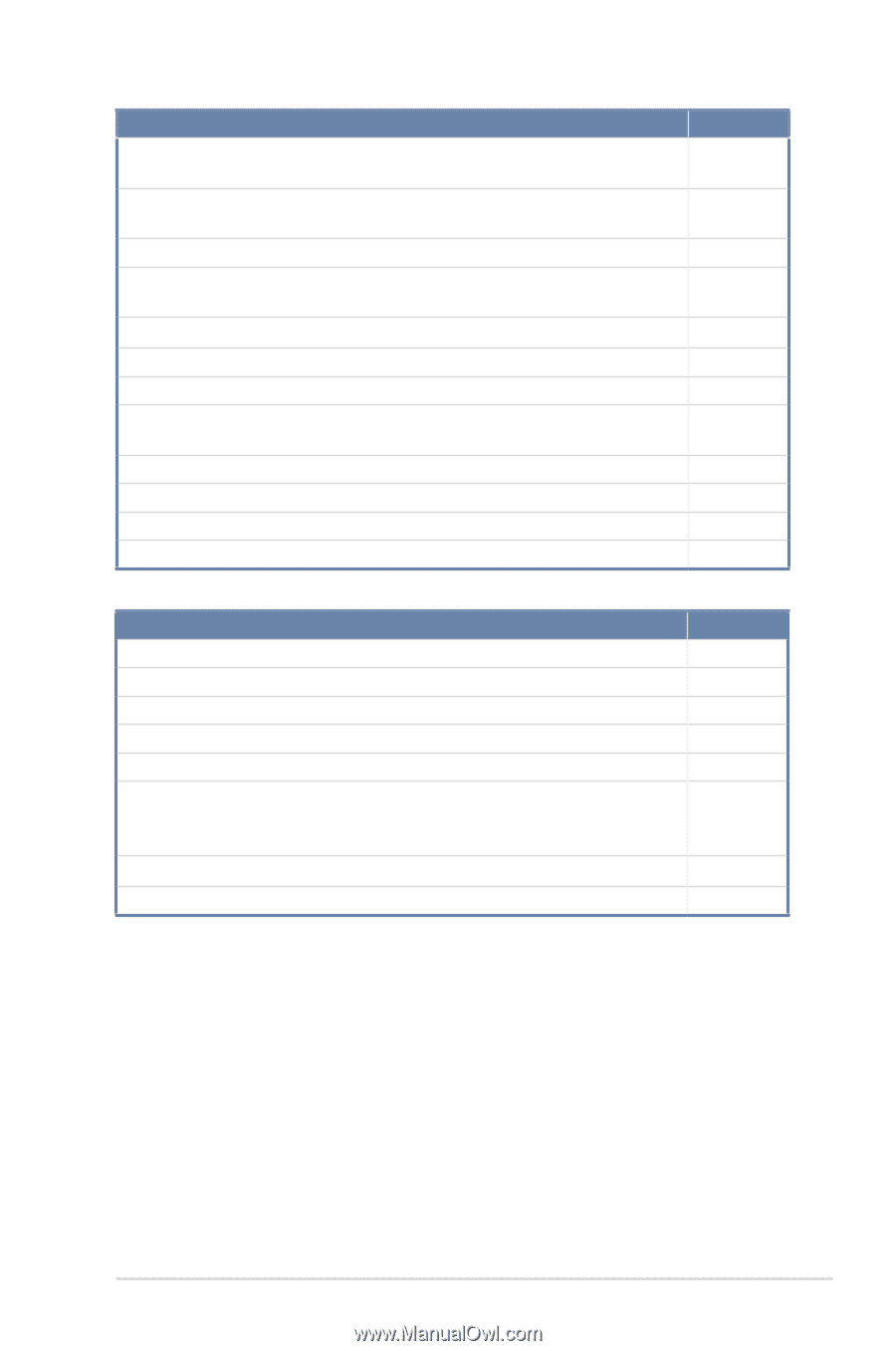
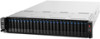
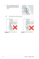
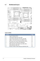
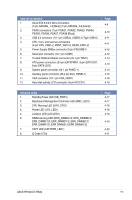
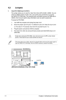
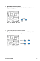
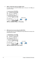
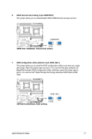
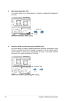
Internal connectors 1. Serial ATA 6.0/3.0 Gb/s connectors (7-pin SATA6G_1-2 [Blue]) (7-pin SATA3G_3-6 [black]) 2. PSAS connectors (7-pin PSAS1, PSAS2, PSAS3, PSAS4, PSAS5, PSAS6, PSAS7, PSAS8 [Blue]) 3. USB 2.0 connector (10-1 pin USB34, USB56; A-Type USB10) 4. CPU, front, and rear fan connectors (4-pin CPU_FAN1-2, FRNT_FAN1-5, REAR_FAN1-2) 5. Power Supply SMBus connector (5-pin PSUSMB1) 6. Serial port connector (10-1 pin COM1) 7. Trusted Platform Module connector (20-1 pin TPM1) 8. ATX power connectors (24-pin EATXPWR1, 8-pin EATX12V1, 8-pin EATX12V2) 9. System panel connector (20-1 pin PANEL1) 10. Auxiliary panel connector (20-2 pin AUX_PANEL1) 11. VGA connector (10-1 pin VGA_HDR1) 12. Hard disk activity LED connector (4-pin HDLED1) Page 4-9 4-10 4-11 4-11 4-12 4-12 4-13 4-13 4-14 4-15 4-16 4-16 Onboard LEDs 1. Standby Power LED (SB_PWR1) 2. Baseboard Management Controller LED (BMC_LED1) 3. CPU Warning LED (ERR_CPU1) 4. Power LED (+5V_LED1) 5. Location LED (LOCLED1) 6. DIMM warning LED (ERR_DIMMA1/2; ERR_DIMMB1/2; ERR_DIMMC1/2; ERR_DIMMD1/2; ERR_DIMME1/2; ERR_DIMMF1/2; ERR DIMMG1/2;ERR DIMMH1/2) 7. CATT LED (CATTERR_LED1) 8. Q-Code LEDs Page 4-17 4-17 4-18 4-18 4-19 4-19 4-20 4-21 ASUS RS720-E7-RS24 4-3
-
 1
1 -
2
-
3
-
4
-
5
-
6
-
7
-
8
-
9
-
10
-
11
-
12
-
13
-
14
-
15
-
16
-
17
-
18
-
19
-
20
-
21
-
22
-
23
-
24
-
25
-
26
-
27
-
28
-
29
-
30
-
31
-
32
-
33
-
34
-
35
-
36
-
37
-
38
-
39
-
40
-
41
-
42
-
43
-
44
-
45
-
46
-
47
-
48
-
49
-
50
-
51
-
 52
52 -
 53
53 -
 54
54 -
 55
55 -
 56
56 -
 57
57 -
 58
58 -
 59
59 -
 60
60 -
 61
61 -
 62
62 -
63
-
64
-
65
-
66
-
67
-
68
-
69
-
70
-
71
-
72
-
73
-
74
-
75
-
76
-
77
-
78
-
79
-
80
-
81
-
82
-
83
-
84
-
85
-
86
-
87
-
88
-
89
-
90
-
91
-
92
-
93
-
94
-
95
-
96
-
97
-
98
-
99
-
100
-
101
-
102
-
103
-
104
-
105
-
106
-
107
-
108
-
109
-
110
-
111
-
112
-
113
-
114
-
115
-
116
-
117
-
118
-
119
-
120
-
121
-
122
-
123
-
124
-
125
-
126
-
127
-
128
-
129
-
130
-
131
-
132
-
133
-
134
-
135
-
136
-
137
-
138
-
139
-
140
-
141
-
142
-
143
-
144
-
145
-
146
-
147
-
148
-
149
-
150
-
151
-
152
-
153
-
154
-
155
-
156
-
157
-
158
-
159
-
160
-
161
-
162
-
163
-
164
-
165
-
166
-
167
-
168
-
169
-
170
-
171
-
172
-
173
-
174
-
175
-
176
-
177
-
178
-
179
-
180
-
181
-
182
-
183
-
184
-
185
-
186
-
187
-
188
-
189
-
190
-
191
-
192
-
193
-
194
-
195
-
196
-
197
-
198
-
199
-
200
-
201
-
202
 |
 |