Asus TS150-E2 User Guide
Asus TS150-E2 Manual
 |
View all Asus TS150-E2 manuals
Add to My Manuals
Save this manual to your list of manuals |
Asus TS150-E2 manual content summary:
- Asus TS150-E2 | User Guide - Page 1
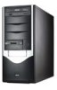
TS150-E2 Pedestal Server - Asus TS150-E2 | User Guide - Page 2
the express written permission of ASUSTeK COMPUTER INC. ("ASUS"). Product warranty or service will not be extended if: (1) the product is BY ASUS. ASUS ASSUMES NO RESPONSIBILITY OR LIABILITY FOR ANY ERRORS OR INACCURACIES THAT MAY APPEAR IN THIS MANUAL, INCLUDING THE PRODUCTS AND SOFTWARE DESCRIBED - Asus TS150-E2 | User Guide - Page 3
Contents Notices vii Safety information viii About this guide ix Chapter 1: Product introduction 1.1 System package contents 1-2 1.2 System specifications 1-3 1.3 Front panel features 1-4 1.4 LED information 1-5 1.5 Rear panel features 1-5 1.6 Internal features 1-6 Chapter 2: Hardware - Asus TS150-E2 | User Guide - Page 4
information 5.1 Managing and updating your BIOS 5-2 5.1.1 Creating a bootable floppy disk 5-2 5.1.2 AFUDOS utility 5-3 5.1.3 ASUS EZ Flash utility 5-6 5.1.4 ASUS CrashFree BIOS 2 utility 5-7 5.1.5 ASUS Update utility 5-9 5.2 BIOS setup program 5-12 5.2.1 BIOS menu screen 5-13 5.2.2 Menu bar - Asus TS150-E2 | User Guide - Page 5
27 5.4.7 PCI PnP 5-28 5.5 Power menu 5-30 5.5.1 ACPI APIC Support 5-30 5.5.2 APM Configuration 5-30 5.5.3 Hardware Monitor 5-32 5.6 Boot 5-35 5.7 Exit menu 5-37 Chapter 6: RAID configuration and driver installation 6.1 RAID configurations 6-2 6.1.1 RAID definitions 6-2 6.1.2 Installing - Asus TS150-E2 | User Guide - Page 6
Contents 6.4 VGA driver installation 6-20 6.4.1 Windows® 2000 Server 6-20 6.4.2 Windows® 2003 Server 6-21 6.4.3 Red Hat® Linux 9.0 6-22 Appendix: Reference information A.1 Simple fixes A-2 A.2 Power supply specification A-4 A.2.1 Input characteristics A-4 A.2.2 Output - Asus TS150-E2 | User Guide - Page 7
. This equipment generates, uses and can radiate radio frequency energy and, if not installed and used in accordance with manufacturer's instructions, may cause harmful interference to radio communications. However, there is no guarantee that interference will not occur in a particular installation - Asus TS150-E2 | User Guide - Page 8
yourself. Contact a qualified service technician or your retailer. Operation safety • Before installing any component to the server, carefully read all the manuals that came with the If you encounter technical problems with the product, contact a qualified service technician or your retailer. viii - Asus TS150-E2 | User Guide - Page 9
, and LAN driver installation for this motherboard. 7. Appendix: Reference information This appendix gives information on the standard or redundant power supply that came with the barebone server. This section also provides a troubleshooting guide for solving common problems when using the - Asus TS150-E2 | User Guide - Page 10
and software products. Refer to the ASUS contact information. 2. Optional documentation Your product package may include optional documentation, such as warranty flyers, that may have been added by your dealer. These documents are not part of the standard package. Conventions used in this guide To - Asus TS150-E2 | User Guide - Page 11
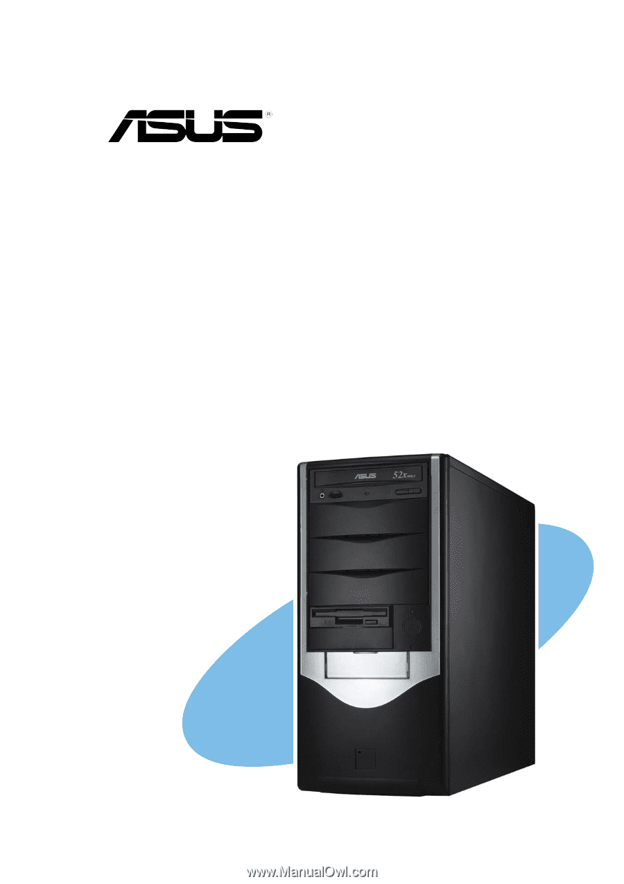
Product introduction Chapter 1 This chapter describes the general features of the barebone server, including sections on the front panel and rear panel specifications. ASUS TS150-E2 1-1 - Asus TS150-E2 | User Guide - Page 12
Item Description 1. ASUS TS150-E2 server with: • ASUS P5CR-VM motherboard • 300 W power supply • Optical drive • Floppy disk drive • Chassis fan • CPU fan and heatsink assembly 2. AC power cord 3. System screws and labels 4. Support CD including drivers and utilities 5. User guide 6. Optional items - Asus TS150-E2 | User Guide - Page 13
1.2 System specifications The ASUS TS150-E2 is a server system featuring the ASUS P5CR-VM motherboard. The server supports the Intel® Pentium® 4 processor in the 775-land package, and includes the latest technologies through the chipsets embedded on the motherboard. Chassis Motherboard Chipset - Asus TS150-E2 | User Guide - Page 14
1.3 Front panel features The TS150-E2 chassis displays a black stylish front panel. The power button, LED indicators, optical, and floppy drives are located on the front panel. Flip the front panel I/O - Asus TS150-E2 | User Guide - Page 15
1.4 LED information The TS150-E2 comes with two LED indicators. Refer to the picture for the LED location and the table below for LED description. Serial port Parallel port VGA port Gigabit LAN ports Power suppy unit 9 cm chassis fan Expansion slots Side cover locking lever ASUS TS150-E2 1-5 - Asus TS150-E2 | User Guide - Page 16
1.6 Internal features The TS150-E2 chassis includes the basic components as shown. 1 2 3 6 7 8 9 4 5 11 10 12 13 14 15 16 1. Power supply 9. Floppy disk drive connector 2. 9 cm chassis fan 10. IDE connector 3. ASUS P5CR-VM motherboard 11. Serial ATA connectors 4. CPU socket 12. Optical - Asus TS150-E2 | User Guide - Page 17
Chapter 2 This chapter lists the hardware setup procedures that you have to perform when installing or removing system components. Hardware setup ASUS TS150-E2 2-1 - Asus TS150-E2 | User Guide - Page 18
unit (CPU) 2. Dual Inline Memory Module(s) (DIMMs) 3. Hard disk drive 4. 5.25-inch drive(s) 5. Expansion card(s) Tool You need a Phillips (cross) screw driver to install some system components. 2.2 Removing the side cover To remove the side cover: 1. Locate the two side cover locks. 1 1 2. Press the - Asus TS150-E2 | User Guide - Page 19
appear as shown in the following picture. Perform the procedures in the succeeding sections to install the CPU, system memory, disk drives, and expansion cards. ASUS TS150-E2 2-3 - Asus TS150-E2 | User Guide - Page 20
2.3 Motherboard information The barebone server comes with the P5CR-VM motherboard already installed. The motherboard is secured to the chassis by eight (8) screws as indicated by the circles in the illustration below. Refer to "Chapter 4 Motherboard information" for detailed information on the - Asus TS150-E2 | User Guide - Page 21
boxed Intel® Pentium® 4 LGA775 processor package should come with installation instructions for the CPU, heatsink, and the retention mechanism. If the instructions in this section do not match the CPU documentation, follow the facing towards you and the load lever is on your left. ASUS TS150-E2 2-5 - Asus TS150-E2 | User Guide - Page 22
2. Press the load lever with your thumb (A), then move it to the left (B) until it is released from the retention tab. Retention tab A Load lever PnP cap B This side of the socket box should face you. To prevent damage to the socket pins, do not remove the PnP cap unless you are installing a - Asus TS150-E2 | User Guide - Page 23
Make sure to enable the Hyper-Threading Technology item in BIOS before installing a supported operating system. • For more information on Hyper-Threading Technology, visit www. appears only if you installed a CPU that supports Hyper-Threading Technology. 3. Reboot the computer. ASUS TS150-E2 2-7 - Asus TS150-E2 | User Guide - Page 24
• When you buy a boxed Intel® Pentium® 4 processor, the package includes the CPU fan and heatsink assembly. • We recommend that you use the ASUS-certified multi-directional heatsink and fan bundled with the system. • If you purchased a separate CPU heatsink and fan assembly, make sure that you have - Asus TS150-E2 | User Guide - Page 25
connector. • If there is only one CPU fan cable, connect it to the connector labeled CPU_FAN1. Failure to do so may cause hardware monitoring errors. ASUS TS150-E2 2-9 - Asus TS150-E2 | User Guide - Page 26
2.5 System memory 2.5.1 Overview The motherboard comes with four Double Data Rate 2 (DDR2) Dual Inline Memory Modules (DIMM) sockets. A DDR2 module has the same physical dimensions as a DDR DIMM but has a 240-pin footprint compared to the 184-pin DDR DIMM. DDR2 DIMMs are notched to match the break - Asus TS150-E2 | User Guide - Page 27
2 4 DIMM_A1 DIMM_B1 DIMM_A2 • • • • • • • • • DIMM_B2 • Install only identical memory modules. For optimum compatibility, do not mix single and double-sided memory modules on the same motherboard. ASUS TS150-E2 2-11 - Asus TS150-E2 | User Guide - Page 28
so that it fits in only one direction. Do not force a DIMM into a socket to avoid damaging the DIMM. • The DDR2 DIMM sockets do not support DDR DIMMs. DO not install DDR DIMMs to the DDR2 DIMM sockets. 2.5.4 Removing a DIMM Follow these steps to remove a DIMM. 1. Simultaneously press the retaining - Asus TS150-E2 | User Guide - Page 29
2.6 Installing a hard disk drive The server system supports one Serial ATA hard disk drive through a detachable hard disk drive cage. You may purchase a second hard disk 1. Press the HDD cage lock while pulling the cage out from the chassis. Place the HDD cage in a flat surface. ASUS TS150-E2 2-13 - Asus TS150-E2 | User Guide - Page 30
2. Insert an HDD to the upper bay of the cage. Make sure that the HDD screw holes are aligned with the HDD cage screw holes. D O N O T install a hard disk drive to the lower bay of the cage. 3. Secure the HDD to the cage with two screws on both sides of the cage. Screw holes 4. Reinstall the HDD - Asus TS150-E2 | User Guide - Page 31
either the SATA power connector O R the legacy 4-pin power connector. D O N O T use both to prevent damage to components and to keep the system from becoming unstable. ASUS TS150-E2 2-15 - Asus TS150-E2 | User Guide - Page 32
2.7 Installing 5.25-inch drives Make sure to unplug the power cable before installing or removing any system components. Failure to do so may cause severe damage to the motherboard and other system components! The system comes with four 5.25-inch drive bays located on the upper front part of the - Asus TS150-E2 | User Guide - Page 33
panel cover hooks. Press the hooks inward until the front panel cover detaches from the chassis. 4 5. Carefully remove the front panel cover, then set aside. 5 ASUS TS150-E2 2-17 - Asus TS150-E2 | User Guide - Page 34
2.7.2 Installing additional optical drive(s) Configure your optical drive as Master/Slave device before installing it to the drive bay. Refer to the optical drive documentation for details. To install an additional optical drive(s): 1 1 1 1. Select the drive bay you intend to use. Push the knock - Asus TS150-E2 | User Guide - Page 35
you used by pressing the hooks inward. Follow the same procedures when installing additional optical drives. 8. Reinstall the front panel and side covers when done. ASUS TS150-E2 2-19 - Asus TS150-E2 | User Guide - Page 36
2.8 Installing expansion cards The system comes with two PCI slots, one PCI Express x8 slot, and one PCI Express x1 slot. Make sure to unplug the power supply before installing or removing an expansion card(s). Failure to do so may cause severe damage to both the motherboard and the components. To - Asus TS150-E2 | User Guide - Page 37
the drive to the bay until it is flushed to the chassis front panel. 2. Align the FDD screw hole with 1 the drive bay lock pin. ASUS TS150-E2 2-21 - Asus TS150-E2 | User Guide - Page 38
3. Move the drive bay lock toward the rear panel to secure the lock. 4. Attach the FDD power and signal cables to the connectors at the 3 back of the drive. 2.9.2 Removing the chassis fan To remove the chassis fan: 1. Disconnect the chassis fan cable from the REAR_FAN1 connector on the - Asus TS150-E2 | User Guide - Page 39
2.10 Connecting cables The TS150-E2 chassis includes the power and signal cables that you need to connect to the motherboard, storage signal cables 8. System fan cables 9. CPU fan cables See "Chapter 4: Motherboard information" or detailed information on motherboard connectors. ASUS TS150-E2 2-23 - Asus TS150-E2 | User Guide - Page 40
2.11 Replacing the side cover After installing all components and re-connecting cables, replace the side cover by following these instructions. 1. Match the side cover hooks to the chassis rail on the side of the chassis. 2 2. Fit the side cover the cover toward the chassis until - Asus TS150-E2 | User Guide - Page 41
Installation options Chapter 3 This chapter describes how to install optional components into the barebone server. ASUS TS150-E2 3-1 - Asus TS150-E2 | User Guide - Page 42
The items required for the optional configurations described in this chapter are not included in the standard barebone system package. These items are purchased separately. 3.1 Second hard disk drive cage The second hard disk drive cage accommodates one IDE or Serial ATA hard disk drive. Second - Asus TS150-E2 | User Guide - Page 43
3. Insert the retention base hooks to the holes until they fit in place. 4. Secure the retention base with two screws. 5. Turn the system upright. ASUS TS150-E2 3-3 - Asus TS150-E2 | User Guide - Page 44
To install a Serial ATA hard disk drive: 1. Insert an HDD to the lower bay of the drive cage. Make sure that the HDD screw holes align with the drive cage screw holes. D O N O T install a hard disk drive to the upper cage of the bay. 2. Secure the HDD to the cage with two screws (with metal washers) - Asus TS150-E2 | User Guide - Page 45
to the power connectors at the back of the drive. Use a Serial ATA power cable and adapter for Serial ATA HDD(s) without a 4-pin power connector. ASUS TS150-E2 3-5 - Asus TS150-E2 | User Guide - Page 46
3.2 Expansion card holder The expansion card holder provides support for long and heavy PCI cards. Install all necessary expansion cards before installing the expansion card holder. Locking lever Assembly Grooves Card holders Adjusting slots - Asus TS150-E2 | User Guide - Page 47
the expansion card holder upright. 3 3. Press the locking lever, then insert the hooks to the chassis holes. 2 4. Secure the expansion card holder with one screw. ASUS TS150-E2 4 3-7 - Asus TS150-E2 | User Guide - Page 48
To hold long expansion cards: 1. Place the card holder at level with the expansion card. Do not use the smaller card holder, which is for long AGP cards. The P5CR-VM motherboard does not have an AGP slot. The other card 2 holders are for long PCI cards. 2. Loosen the screw(s) to adjust the - Asus TS150-E2 | User Guide - Page 49
Motherboard info Chapter 4 This chapter gives information about the motherboard that comes with the server. This chapter includes the motherboard layout, jumper settings, and connector locations. ASUS TS15-E2 3-1 - Asus TS150-E2 | User Guide - Page 50
24.5cm (9.6in) 4.1 Motherboard layout PS/2KBMS KBPWR1 T: Mouse B: Keyboard USB12 USBPW12 COM1 ATXPWR1 PSUSMB1 24.5cm (9.6in) FM_CPU1 CPU_FAN1 Intel® E7221 LGA775 ATX12V1 PARALLEL PORT VGA1 LAN1 DDR2 DIMM_A1 (64 bit,240-pin module) DDR2 DIMM_A2 (64 bit,240-pin module) FM_CPU2 CPU_FAN2 - Asus TS150-E2 | User Guide - Page 51
4. USB 2.0 ports 1 and 2 5. Serial (COM1) port 6. VGA port 7. LAN 1 (RJ-45) port 8. LAN 2 (RJ-45) port Page 4-10 4-10 4-10 4-10 4-10 4-10 4-10 4-10 ASUS TS150-E2 4-3 - Asus TS150-E2 | User Guide - Page 52
Internal connectors Page 1. Floppy disk drive connector (34-1 pin FLOPPY1) 4-9 2. IDE connector (40-1 pin PRI_IDE1)) 4-10 3. Serial ATA connectors (7-pin SATA1, SATA2, SATA3, SATA4) 4-11 4. CPU fan connectors (4-pin CPU_FAN1/CPU_FAN2)) 4-12 5. System fan connectors (3-pin REAR_FAN1/ - Asus TS150-E2 | User Guide - Page 53
on CLRTC jumper default position. Removing the cap will cause system boot failure! P5CR-LS P5CR-VM Clear RTC RAM CLRTC1 1 2 Normal (Default) 2 3 Clear CMOS ASUS TS150-E2 4-5 - Asus TS150-E2 | User Guide - Page 54
2 . CPU fan mode selection (3-pin FM_CPU1, FM_CPU2) These jumpers allow you to connect either a 3-pin or a 4-pin fan cable plug to the CPU fan connectors (CPU_FAN1, CPU_FAN2). Set these jumpers to pins 1-2 if you are using a 3-pin fan cable plug, or to pins 2-3 if you are using a 4-pin plug. P5CR- - Asus TS150-E2 | User Guide - Page 55
onboard Broadcom BCM5721 Gigabit LAN controller. Set to pins 1-2 to activate the Gigabit LAN feature. P5CR-LS P5CR-VM LAN_EN1 setting LAN_EN1 2 1 Enable (Default) 3 2 Disable ASUS TS150-E2 4-7 - Asus TS150-E2 | User Guide - Page 56
6 . Gigabit LAN controller setting (3-pin LAN_EN2) These jumpers allow you to enable or disable the onboard Broadcom BCM5705E Gigabit LAN controller. Set to pins 1-2 to activate the Gigabit LAN feature. P5CR-LS P5CR-VM LAN_EN2 setting LAN_EN2 21 32 Enable (Default) Disable 4-8 Chapter 4: - Asus TS150-E2 | User Guide - Page 57
the boot process and enter BIOS setup to re-enter data. RECOVERY1 12 23 P5CR-LS P5CR-VM BIOS recovery setting Normal (Default) BIOS Recovery ASUS TS150-E2 4-9 - Asus TS150-E2 | User Guide - Page 58
4.3 Connectors 4.3.1 Rear panel connectors 1 2 3 4 5 6 7 8 1 . P S / 2 m o u s e p o r t ( g r e e n ) . This port is for a PS/2 mouse. 2 . P a r a l l e l p o r t . This 25-pin port connects a parallel printer, a scanner, or other devices. 3 . P S / 2 k e y b o a r d p o r t ( p u r p l e - Asus TS150-E2 | User Guide - Page 59
with a covered Pin 5. FLOPPY1 PIN 1 P5CR-VM NOTE: Orient the red markings on the floppy ribbon cable to PIN 1. P5CR-VM Floppy disk drive connector ASUS TS150-E2 4-11 - Asus TS150-E2 | User Guide - Page 60
2 . IDE connector (40-1 pin PRI_IDE1) This connector is for an Ultra DMA 100/66 signal cable. The Ultra DMA 100/66 signal cable has three connectors: a blue connector for the primary IDE connector on the motherboard, a black connector for an Ultra DMA 100/66 IDE slave device (optical drive/hard disk - Asus TS150-E2 | User Guide - Page 61
RSATA_RXN4 GND SATA1 SATA2 SATA3 SATA4 Important notes on Serial ATA • You must install Windows® 2000 Service Pack 4, Windows® 2000 Advanced Server, or Windows® Server 2003 before using Serial ATA hard disk Use SATA1, SATA2 SATA3, SATA4 Master Slave Boot disk Data disk ASUS TS150-E2 4-13 - Asus TS150-E2 | User Guide - Page 62
4 . CPU and system fan connectors (4-pin CPU_FAN1/2, REAR_FAN1/2, FRNT_FAN1/2) The fan connectors support cooling fans of 350 mA ~ 740 mA (8.88 W max.) or a total of 2.1 A ~ 4.44 A (53.28 W max.) at +12V. Connect the fan cables to the fan - Asus TS150-E2 | User Guide - Page 63
to a slot opening at the back of the system chassis. The USB connectors comply with USB 2.0 specification that supports up to 480 Mbps connection speed. USB34 USB56 USB78 P5CR-VM P5CR-VM USB 2.0 connectors Never connect a 1 USB+5V USB_5USB_5+ USB+5V USB+5V USB_7USB_7+ USB+5V ASUS TS150-E2 4-15 - Asus TS150-E2 | User Guide - Page 64
7 . S S I power connectors (24-pin ATXPWR1, 4- p i n A T X 1 2V1 ) These connectors are for SSI power supply plugs. The power supply plugs are designed to fit these connectors in only one orientation. Find the proper orientation and push down firmly until the connectors completely fit. • Use of an - Asus TS150-E2 | User Guide - Page 65
with an SMBus host and/or other SMBus devices using the SMBus interface. P5CR-VM P5CR-VM SMBus connector BPSMB1 1 NC I2C_6_CLK# GND I2C_6_DATA# +5V ASUS TS150-E2 4-17 - Asus TS150-E2 | User Guide - Page 66
using the SMBus interface. PSUSMB1 P5CR-VM P5CR-VM Power supply SMBus connector 11. BMC connector (16-pin BMCCONN1) This connector is for an ASUS server management card. BMCCONN1 P5CR-VM P5CR-VM BMC connector +5VSB +5VSB BMC SMBCLK 12CCLK1 PSON# BMC_RST# PWROK PSONEN# +5VSB +5VSB BMC SMBDATA - Asus TS150-E2 | User Guide - Page 67
12. TRPWR connector (2-pin TRPWR1) This connector is for an internal temperature sensor/probe. SENSER GND P5CR-VM P5CR-VM TRPWR connector 1 TRPWR1 ASUS TS150-E2 4-19 - Asus TS150-E2 | User Guide - Page 68
13. Auxiliary panel connector (20-pin AUX_PANEL1) This connector supports several server system functions. AUX_PANEL1 P5CR-VM LAN2_LINKACTLEDLAN2_LINKACTLED+ LAN1_LINKACTLED+ LAN1_LINKACTLED- +5VSB I2CDATA_P0 GND I2CCLK_P0 NC P5CR-VM Auxiliary panel connector +5VSB AUX_BMCLOCLED# GND - Asus TS150-E2 | User Guide - Page 69
14. System panel connector (20-pin PANEL1) This connector supports several chassis-mounted functions. +5V NC FP_PLED +3VSB FP_MLED NC +5V GND GND SPEAKER FP_HDLED+ 2-pin connector is for the chassis-mounted reset button for system reboot without turning off the system power. ASUS TS150-E2 4-21 - Asus TS150-E2 | User Guide - Page 70
4-22 Chapter 4: Motherboard information - Asus TS150-E2 | User Guide - Page 71
Chapter 5 This chapter tells how to change system settings through the BIOS Setup menus and describes the BIOS parameters. BIOS information ASUS AP1710-E1 3-1 - Asus TS150-E2 | User Guide - Page 72
h F r e e B I O S 2 (Updates the BIOS using a bootable floppy disk or the motherboard support CD when the BIOS file fails or gets corrupted.) 4. A S U S U p d a t e ( in the future. Copy the original motherboard BIOS using the ASUS Update or AFUDOS utilities. 5.1.1 Creating a bootable floppy disk - Asus TS150-E2 | User Guide - Page 73
is your optical drive letter. e. Press , then follow screen instructions to continue. 2. Copy the original or the latest motherboard BIOS file . 1. Copy the AFUDOS utility (afudos.exe) from the motherboard support CD to the bootable floppy disk you created earlier. 2. Boot ASUS TS150-E2 5-3 - Asus TS150-E2 | User Guide - Page 74
(www.asus.com) and download the latest BIOS file for the motherboard. Save the BIOS file to a bootable floppy disk. Write the BIOS filename on a piece of paper. You need to type the exact BIOS filename at the DOS prompt. 2. Copy the AFUDOS utility (afudos.exe) from the motherboard support CD to - Asus TS150-E2 | User Guide - Page 75
hard disk drive. A:\>afudos /iP5CR-VM.ROM /pbnc AMI Firmware Update Utility - Version 1.19(ASUS V2.07(03.11.24BB)) Copyright (C) 2002 American Megatrends, Inc. All rights reserved. WARNING!! Writing flash ...... done Verifying flash .... done Please restart your computer A:\> ASUS TS150-E2 5-5 - Asus TS150-E2 | User Guide - Page 76
it is accessible by pressing + during the Power-On Self Tests (POST). To update the BIOS using EZ Flash: 1. Visit the ASUS website (www.asus.com) to download the latest BIOS file for the motherboard and rename the same to P 5 C R - V M . R O M. 2. Save the BIOS file to a floppy disk, then - Asus TS150-E2 | User Guide - Page 77
can update a corrupted BIOS file using the motherboard support CD or the floppy disk that contains the updated BIOS file. • Prepare the motherboard support CD or the floppy disk containing the updated ! 4. Restart the system after the utility completes the updating process. ASUS TS150-E2 5-7 - Asus TS150-E2 | User Guide - Page 78
from the floppy disk drive, then turn on the system. 2. Insert the support CD to the optical drive. 3. The utility displays the following message and BIOS version for this motherboard. Visit the ASUS website (www.asus.com) to download the latest BIOS file. 5-8 Chapter 5: Motherboard information - Asus TS150-E2 | User Guide - Page 79
optical drive. The D r i v e r s menu appears. 2. Click the U t i l i t i e s tab, then click I n s t a l l A S U S U p d a t e . V X . X X . X X. 3. The ASUS Update utility is copied to your system. Quit all Windows® applications before you update the BIOS using this utility. ASUS TS150-E2 5-9 - Asus TS150-E2 | User Guide - Page 80
utility from the Windows® desktop by clicking S t a r t > P r o g r a m s > A S U S > A S U S U p d a t e > A S U S U p d a t e. The ASUS Update main window appears. 2. Select U p d a t e B I O S f r o m 3. Select the ASUS FTP site t h e I n t e r n e t option from the nearest you to avoid - Asus TS150-E2 | User Guide - Page 81
a t e. The ASUS Update main window appears. 2. Select U p d a t e B I O S f r o m a f i l e option from the drop-down menu, then click N e x t. 3. Locate the BIOS file from the O p e n window, then click S a v e. 4. Follow the screen instructions to complete the update process. ASUS TS150-E2 5-11 - Asus TS150-E2 | User Guide - Page 82
5.2 BIOS setup program This motherboard supports a programmable firmware chip that you can update using the provided exactly match what you see on your screen. • Visit the ASUS website (www.asus.com) to download the latest BIOS file for this motherboard. 5-12 Chapter 5: Motherboard information - Asus TS150-E2 | User Guide - Page 83
Fourth IDE Slave IDE Configuration System Information [16:37:21] [Wed,10/10/2004] [1.44M, 3.5 in.] [ST320410A] : [ASUS CD-S520/A] : [Not Detected] : [Not Detected] : [Not Detected] : [Not Detected] Use [ENTER], [TAB] or the navigation keys differ from one screen to another. ASUS TS150-E2 5-13 - Asus TS150-E2 | User Guide - Page 84
IDE Slave Fourth IDE Master Fourth IDE Slave IDE Configuration System Information [16:37:21] [Wed, 10/10/2004] [1.44M, 3.5 in] : [ST320410A] : [ASUS CD-S520/A] : [Not Detected] : [Not Detected] : [Not Detected] : [Not Detected] Main menu items A solid triangle before each item on any menu screen - Asus TS150-E2 | User Guide - Page 85
IDE Configuration System Information [16:37:21] [Wed,10/10/2004] [1.44M, 3.5 in.] : [ST320410A] : [ASUS CD-S520/A] : [Not Detected] : [Not Detected] : [Not Detected] : [Not Detected] Use [ENTER], [TAB 5.25 in.] [1.2M, 5.25 in.] [720K, 3.5 in.] [1.44M, 3.5 in.] [2.88M, 3.5 in.] ASUS TS150-E2 5-15 - Asus TS150-E2 | User Guide - Page 86
] [Auto] [CDROM] [ARMD] LBA/Large Mode [Auto] Enables or disables the LBA mode. Setting to Auto enables the LBA mode if the device supports this mode, and if the device was not previously formatted with LBA mode disabled. Configuration options: [Disabled] [Auto] Block (Multi-sector Transfer) [Auto - Asus TS150-E2 | User Guide - Page 87
if you want to configure the item. IDE Configuration Configure SATA As Onboard IDE Operate Mode Enhanced Mode Support On IDE Detect Time Out (Sec) [Standard IDE] [Enhanced Mode] [S-ATA] [35] When in 2000/XP. Configuration options: [Disabled] [Compatible Mode] [Enhanced Mode] ASUS TS150-E2 5-17 - Asus TS150-E2 | User Guide - Page 88
and P-ATA options are for advanced users only. If you set to any of these options and encounter problems, revert to the default setting S A T A. Configuration options: [S-ATA+P-ATA] [S-ATA] [P-ATA Stagger Spinup Support [Disabled] Enables or disables the stagger spinup support. Configuration options - Asus TS150-E2 | User Guide - Page 89
: 504 MB AMI BIOS Displays the auto-detected BIOS information. Processor Displays the auto-detected CPU specification. System Memory Displays the auto-detected system memory. ASUS TS150-E2 5-19 - Asus TS150-E2 | User Guide - Page 90
to display the configuration options. USB Configuration Module Version - 2.23.2-9.4 USB Devices Enabled: None USB Function Legacy USB Support USB 2.0 Controller USB 2.0 Controller Mode [Enabled] [Auto] [Enabled] [HiSpeed] Enables USB host controllers. The M o d u l e V e r s i o n and - Asus TS150-E2 | User Guide - Page 91
USB controller legacy mode is enabled. If no USB device is detected, the legacy USB support is disabled. Configuration options: [Disabled] [Enabled] [Auto] USB 2.0 Controller [Enabled] Revision [1.4] Allows you to choose the MPS revision. Configuration options: [1.1] [1.4] ASUS TS150-E2 5-21 - Asus TS150-E2 | User Guide - Page 92
Port Mode Flow Control Redirection after BIOS POST Terminal Type VT-UTF8 Combo Key Support Sredir Memory Display Delay [COM1] [3F8h, 4] [115200, 8,n,1] [None] the flow control for console redirection. Configuration options: [None [Hardware] [Software] 5-22 Chapter 5: Motherboard information - Asus TS150-E2 | User Guide - Page 93
Configuration options: [ANSI] [VT100] [VT-UTF8] VT-UTF8 Combo Key Support [Enabled] Enables or disables the VT-UTF8 combo key support for ANSI or VT100 terminals. Configuration options: [Disabled] [Enabled] Sredir detected by BIOS. Use the or keys to adjust the values. ASUS TS150-E2 5-23 - Asus TS150-E2 | User Guide - Page 94
: [Disabled] [Enabled] Enhanced C1 Control [Auto] When set to [Auto], the BIOS will automatically check the CPU's capability to enable the C1E support. In C1E mode, the CPU power consumption is lower when idle. Configuration options: [Auto] [Disabled] CPU Internal Thermal Control [Auto] Disables or - Asus TS150-E2 | User Guide - Page 95
are set according to the DRAM SPD (Serial Presence Detect). When disabled, you can manually set the DRAM timing parameters through the DRAM sub-items. Configuration options: [Disabled] DRAM write recovery time. Configuration options: [2 Clocks] [3 Clocks] [4 Clocks] [5 Clocks] ASUS TS150-E2 5-25 - Asus TS150-E2 | User Guide - Page 96
you to enable or disable DRAM timing. Configuration options: [Auto] [Disabled] Hyper Path 2 [Auto] Allows you to enable or disable the ASUS Hyper Path 2 feature. Configuration options: [Disabled] [Enabled] [Auto] Booting Graphic Priority [Internal VGA] Allows selection of the graphics controller to - Asus TS150-E2 | User Guide - Page 97
item appears only when the P a r a l l e l P o r t M o d e is set to E P P. Configuration options: [1.9] [1.7] Parallel Port IRQ [IRQ7] Allows selection of the Parallel Port IRQ. Configuration options: [IRQ5] [IRQ7] ASUS TS150-E2 5-27 - Asus TS150-E2 | User Guide - Page 98
5.4.7 PCI PnP The PCI PnP menu items allow you to change the advanced settings for PCI/PnP devices. The menu includes setting IRQ and DMA channel resources for either PCI/PnP or legacy ISA devices, and setting the memory size block for legacy ISA devices. Take caution when changing the settings of - Asus TS150-E2 | User Guide - Page 99
] [Reserved] Active State Power-Management [Enabled] Allows you to enable or disable the PCI Express L0s and L1 link power states. Configuration options: [Disabled] [Enabled] ASUS TS150-E2 5-29 - Asus TS150-E2 | User Guide - Page 100
Select an item then press to display the configuration options. ACPI APIC Support APM Configuration Hardware Monitor [Enabled] Select the ACPI state used for System Suspend. 5.5.1 ACPI APIC Support [Enabled] Allows you to enable or disable the Advanced Configuration and Power Interface - Asus TS150-E2 | User Guide - Page 101
to turn on the system. This feature requires an ATX power supply that provides at least 1A on the +5VSB lead. Configuration options: [Disabled] [Enabled] ASUS TS150-E2 5-31 - Asus TS150-E2 | User Guide - Page 102
(RPM). If the fan is not connected to the motherboard, the field shows N/A. Smart Fan Control [Disabled] Allows you to enable or disable the ASUS Smart Fan feature that smartly adjusts the fan speeds for more efficient system operation. When this field is set to [Enabled], the three succeeding items - Asus TS150-E2 | User Guide - Page 103
Priority 1st Boot Device 2nd Boot Device 3rd Boot Device [1st FLOPPY DRIVE] [PM-ST320410A] [PS-ASUS CD-S520/A] Specifies the boot sequence from the availabe devices. 1st ~ xxth Boot Device [1st devices installed in the system. Configuration options: [xxxxx Drive] [Disabled] ASUS TS150-E2 5-33 - Asus TS150-E2 | User Guide - Page 104
[Disabled] [Enabled] Set this item to [Enabled] to use the ASUS MyLogo™ feature. Add On ROM Display Mode [Force BIOS] Sets the the NumLock. Configuration options: [Off] [On] PS/2 Mouse Support [Auto] Allows you to enable or disable support for PS/2 mouse. Configuration options: [Disabled] [Enabled] - Asus TS150-E2 | User Guide - Page 105
same steps as in setting a user password. To clear the supervisor password, select the Change Supervisor Password then press . The message "Password Uninstalled" appears. ASUS TS150-E2 5-35 - Asus TS150-E2 | User Guide - Page 106
If you forget your BIOS password, you can clear it by erasing the CMOS Real Time Clock (RTC) RAM. See section "4.6 Jumpers" for information on how to erase the RTC RAM. After you have set a supervisor password, the other items appear to allow you to change other security settings. Security Settings - Asus TS150-E2 | User Guide - Page 107
operation. Pressing does not immediately exit this menu. Select one of the options from this menu or from the legend bar to exit. ASUS TS150-E2 5-37 - Asus TS150-E2 | User Guide - Page 108
Exit & Save Changes Once you are finished making your selections, choose this option from the Exit menu to ensure the values you selected are saved to the CMOS RAM. An onboard backup battery sustains the CMOS RAM so it stays on even when the PC is turned off. When you select this option, a - Asus TS150-E2 | User Guide - Page 109
RAID configuration Chapter 6 This chapter provides information on RAID configurations, RAID driver installation, and LAN driver installation for this motherboard. ASUS TS15-E2 3-1 - Asus TS150-E2 | User Guide - Page 110
to a second drive. If one drive fails, the disk array management software directs all applications to the surviving drive as it contains a complete included in a created RAID set, copy first the RAID driver from the support CD to a floppy disk before you install an operating system to the selected - Asus TS150-E2 | User Guide - Page 111
supports hard disks into the drive bays following the instructions in the system user guide. 2. Connect a SATA signal cable to R A I D O p t i o n R O M embedded in the Southbridge chip. Refer to the succeeding sections for details on how to enter the RAID configuration utility. ASUS TS150-E2 6-3 - Asus TS150-E2 | User Guide - Page 112
and RAID 1 set(s) from SATA hard disk drives that are connected to the SATA connectors supported by the motherboard Southbridge chip. To enter the Intel® Application Accelerator RAID Option ROM utility: [ESC] Previous Menu [Enter]-Select 6-4 Chapter 6: RAID configuration and driver installation - Asus TS150-E2 | User Guide - Page 113
array block size is recommended. For multimedia computer systems used mainly for audio and video editing, a higher array block size is recommended for optimum performance. ASUS TS150-E2 6-5 - Asus TS150-E2 | User Guide - Page 114
to create this volume (Y/N) 7. Select [4 . E x i t], then press to exit the RAID configuration utility. Press when the utility displays a confirmation window. 6-6 Chapter 6: RAID configuration and driver installation - Asus TS150-E2 | User Guide - Page 115
LOST!! Are you sure you want to delete volume "RAID_Volume0"? (Y/N) 4. Press to delete the RAID set; otherwise, press to return to the utility main menu. ASUS TS150-E2 6-7 - Asus TS150-E2 | User Guide - Page 116
the drive; otherwise, press to return to the utility main menu. 5. Follow steps 2-4 to select and reset other RAID set drives. 6-8 Chapter 6: RAID configuration and driver installation - Asus TS150-E2 | User Guide - Page 117
screen. Warning!! Bootable CD will delete all data in floppy Press a key to continue._ 6. Press any key to continue. The RAID drivers are copied to the floppy disk. 7. Eject the floppy disk, then write-protect it to prevent computer virus infection. 8. Press any key to continue. ASUS TS150-E2 6-9 - Asus TS150-E2 | User Guide - Page 118
the contents of the support CD to locate the driver disk utility. The RAID driver disk for the Intel® ICH6R is located in: \Drivers\Chipset\Intel\IAA\F6 Install Floppy\F6flpy32 3. Insert a formatted high-density floppy disk to the floppy disk drive. 4. Follow screen instructions to complete the - Asus TS150-E2 | User Guide - Page 119
OS installation To install the Intel® ICH6R RAID controller driver when installing Windows® 2000/2003 Server OS: 1. a l l a t h i r d p a r t y S C S I o r R A I D d r i v e r . . ." appears at the bottom of the screen. 3. When prompted, press to specify an additional device. ASUS TS150-E2 6-11 - Asus TS150-E2 | User Guide - Page 120
to select. 6. The Windows® 2000/2003 Setup loads the RAID controller drivers from the RAID driver disk. When prompted, press to continue installation. 7. Setup then proceeds with the OS installation. Follow screen instructions to continue. 6-12 Chapter 6: RAID configuration and - Asus TS150-E2 | User Guide - Page 121
earlier to the floppy disk drive. 9. Select the option "S e a r c h f o r a s u i t a b l e d r i v e r f o r m y d e v i c e ( r e c o m m e n d e d ), then click N e x t. 10. The wizard searches the RAID controller drivers. When found, click N e x t to install the drivers. ASUS TS150-E2 6-13 - Asus TS150-E2 | User Guide - Page 122
installation is done. To verify the Intel® ICH6R RAID controller driver installation: 1. Right-click the M y C o m p u t e r icon on the Windows® desktop , then select P r o p e r t i e s from the menu. 2. Click the H a r d w a r e tab, then click the D e v i c e M a n a g e r button. 3. Click - Asus TS150-E2 | User Guide - Page 123
If A u t o r u n is NOT enabled in your computer, browse the contents of the support CD to locate the file ASSETUP.EXE from the BIN folder. Double-click the A S S E T U P . E X E to run the CD. 3. Click the B r o a d c o m 5 7 2 1 L A N D r i v e r option to begin installation. ASUS TS150-E2 6-15 - Asus TS150-E2 | User Guide - Page 124
4. Click N e x t when the InstallShield Wizard window appears. Follow screen instructions to continue installation. 6-16 Chapter 6: RAID configuration and driver installation - Asus TS150-E2 | User Guide - Page 125
, click O K. When the drivers are successfully installed, the LAN adapter appears in the N e t w o r k window. 10. Click C l o s e. The T C P / I P P r o p e r t i e s window appears. 11. Configure the TCP/IP protocol, then click O K. 12. Restart the computer when prompted. ASUS TS150-E2 6-17 - Asus TS150-E2 | User Guide - Page 126
Red Hat® Linux 9.0 Follow these instructions when installing the Broadcom® Gigabit LAN controller base driver for the Red Hat® Linux version the binary driver for your kernel: cd /usr/src/{redhat,OpenLinux,turbo,packages,rpm ..} rpm -bb SPECS/bcm5700.spec or rpmbuild -bb SPECS/ bcm5700.spec The RPM - Asus TS150-E2 | User Guide - Page 127
3. Test the driver by loading it: insmod bcm5700.o 4. Install the driver and man page: make install See the RPM instructions on the previous page for the location of the installed driver. 5. Refer to Linux distribution documentation to configure the network protocol and address. ASUS TS150-E2 6-19 - Asus TS150-E2 | User Guide - Page 128
This section provides instructions on how to install the Intel® E7221 Super Video Graphics Adapter (SVGA) driver. 6.4.1 Windows® 2000 Server You need to manually install the Intel® E7221 SVGA driver on a Windows® 2000 Server operating system. To install the Intel® E7221 SVGA driver: 1. Restart the - Asus TS150-E2 | User Guide - Page 129
additional driver(s) to support the onboard VGA. Verifying the VGA driver installation To verify if the Intel® E7221 SVGA driver is s from the menu. 5. Click the A d a p t e r tab, then click the p r o p e r t i e s button to display the VGA drivers. 6. Click O K when finished. ASUS TS150-E2 6-21 - Asus TS150-E2 | User Guide - Page 130
Red Hat® Linux 9.0 The Red Hat® Linux 9.0 (2.4.x kernels) operating system automatically recognizes the Intel® E7221 SVGA driver during system installation. There is no need to install an additional driver(s) to support the onboard VGA. 6-22 Chapter 6: RAID configuration and driver installation - Asus TS150-E2 | User Guide - Page 131
Reference information Appendix This appendix gives information on the standard and redundant power supply that came with the barebone server. This section also provides a troubleshooting guide for solving common problems when using the barebone server. ASUS TS150-E2 3-1 - Asus TS150-E2 | User Guide - Page 132
on the system or the components. These problems only requires simple troubleshooting actions that you can perform by yourself. Problem Action The power LED on the server or the DIMMs the system turned on supports. 2. Make sure that the DIMMs are properly installed on the sockets. A-2 - Asus TS150-E2 | User Guide - Page 133
Problem Action T h e s y s t e m c o n t i n u o u s l y 1. Check the memory modules beeps after it was turned and make sure you installed on supported DIMMs. 2. Make sure that the DIMMs are properly installed on the sockets. T the LAN drivers from the support CD. ASUS TS150-E2 A-3 - Asus TS150-E2 | User Guide - Page 134
A.2 Power supply specification A.2.1 Input characteristics Parameter Input Voltage Range Nominal Voltage Current Nominal Vin Frequency Voltage Range 230V Min 180 V 200 V 47 Hz Max 265 V 240 V 4.0 A 63 Hz A.2.2 Output Characteristics Outputs +5 V +12 V1 +3.3 V -12 V +5V stb +12V2 Min 0.5 A
-
 1
1 -
 2
2 -
 3
3 -
 4
4 -
 5
5 -
 6
6 -
 7
7 -
8
-
9
-
10
-
11
-
12
-
13
-
14
-
15
-
16
-
17
-
18
-
19
-
20
-
21
-
22
-
23
-
24
-
25
-
26
-
27
-
28
-
29
-
30
-
31
-
32
-
33
-
34
-
35
-
36
-
37
-
38
-
39
-
40
-
41
-
42
-
43
-
44
-
45
-
46
-
47
-
48
-
49
-
50
-
51
-
52
-
53
-
54
-
55
-
56
-
57
-
58
-
59
-
60
-
61
-
62
-
63
-
64
-
65
-
66
-
67
-
68
-
69
-
70
-
71
-
72
-
73
-
74
-
75
-
76
-
77
-
78
-
79
-
80
-
81
-
82
-
83
-
84
-
85
-
86
-
87
-
88
-
89
-
90
-
91
-
92
-
93
-
94
-
95
-
96
-
97
-
98
-
99
-
100
-
101
-
102
-
103
-
104
-
105
-
106
-
107
-
108
-
109
-
110
-
111
-
112
-
113
-
114
-
115
-
116
-
117
-
118
-
119
-
120
-
121
-
122
-
123
-
124
-
125
-
126
-
127
-
128
-
129
-
130
-
131
-
132
-
133
-
134
 |
 |
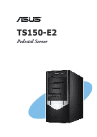
TS150-E2
Pedestal Server