Asus TS150-E2 User Guide - Page 32
Installing 5.25-inch drives
 |
View all Asus TS150-E2 manuals
Add to My Manuals
Save this manual to your list of manuals |
Page 32 highlights
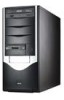
2.7 Installing 5.25-inch drives Make sure to unplug the power cable before installing or removing any system components. Failure to do so may cause severe damage to the motherboard and other system components! The system comes with four 5.25-inch drive bays located on the upper front part of the chassis. An 1 optical drive that comes standard with the system package occupies 2 the uppermost bay (labeled 1). The lower bays (labeled 2, 3, and 4) are 3 available for additional 5.25-inch optical, zip, or floppy disk drives. 4 You must remove the front panel cover before installing a 5.25-inch drive(s). 2.7.1 Removing the front panel cover To remove the front panel cover: 1 1. Locate and remove two screws that secure the left side cover to the chassis. Keep the screw for later use. 2 2. Slightly pull the cover toward the direction of the rear panel until it disengages from the chassis. Set the cover aside. 2-16 Chapter 2: Hardware setup
-
 1
1 -
2
-
3
-
4
-
5
-
6
-
7
-
8
-
9
-
10
-
11
-
12
-
13
-
14
-
15
-
16
-
17
-
18
-
19
-
20
-
21
-
22
-
23
-
24
-
25
-
26
-
 27
27 -
 28
28 -
 29
29 -
 30
30 -
 31
31 -
 32
32 -
 33
33 -
 34
34 -
 35
35 -
 36
36 -
 37
37 -
38
-
39
-
40
-
41
-
42
-
43
-
44
-
45
-
46
-
47
-
48
-
49
-
50
-
51
-
52
-
53
-
54
-
55
-
56
-
57
-
58
-
59
-
60
-
61
-
62
-
63
-
64
-
65
-
66
-
67
-
68
-
69
-
70
-
71
-
72
-
73
-
74
-
75
-
76
-
77
-
78
-
79
-
80
-
81
-
82
-
83
-
84
-
85
-
86
-
87
-
88
-
89
-
90
-
91
-
92
-
93
-
94
-
95
-
96
-
97
-
98
-
99
-
100
-
101
-
102
-
103
-
104
-
105
-
106
-
107
-
108
-
109
-
110
-
111
-
112
-
113
-
114
-
115
-
116
-
117
-
118
-
119
-
120
-
121
-
122
-
123
-
124
-
125
-
126
-
127
-
128
-
129
-
130
-
131
-
132
-
133
-
134
 |
 |
