Asus TUSI-M TUSI-M User Manual - Page 15
Layout Contents - cpu support
 |
View all Asus TUSI-M manuals
Add to My Manuals
Save this manual to your list of manuals |
Page 15 highlights
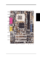
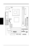
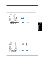
3. H/W SETUP Layout Contents 3. HARDWARE SETUP 3.2 Layout Contents Motherboard Settings 1) JEN 2) USBPWR0/USBPWR1 3) FS3, FS1, FS2, FS0 Expansion Slots 1) DIMM1, DIMM2 2) CPU Socket 370 3) PCI1, PCI2, PCI3 4) AMR Connectors 1) PS2KBMS 2) PS2KBMS 3) RJ-45 4) USB 5) PARALLEL 6) COM1/COM2 7) VGA1 8) GAME_AUDIO 9) GAME_AUDIO 10) PRIMARY/SECONDARYIDE 11) FLOPPY 12) PLED 13) PWR, CPU, CH_FAN 14) WOR 15) WOL_CON 16) USB1, USB2 17) CD1, AUX, MODEM 18) AFPANEL 19) AAPANEL 20) ATXPWR 21) PWRTMP 22) SPEAKER 23) KEYLOCK 24) PLED 25) MLED 26) SMI 27) PWR BUTTON 28) RESET p.17 JumperFree Mode Setting (Enable/Disable) p.17 USB Power Up Settings (Enable/Disable) p.18 CPU External Frequency Selection p.20 168 Pin DIMM Memory Support p.22 Central Processing Unit p.23 32-bit PCI Bus Expansion Slots p.25 Audio Modem Riser Slot p.26 PS/2 Mouse Connector (6 pin female) p.26 PS/2 Keyboard Connector (6 pin female) p.27 Fast-Ethernet Port Connector p.27 Universal Serial Bus Ports 0 & 1 (Two 4 pin female) p.27 Parallel Port Connector (25 pin female) p.28 Serial Port Connectors (9 pins, 10-1 pin) p.28 Monitor Port Connector (15 pin female) p.29 Game/MIDI Connector (15 pin female) (optional) p.29 Audio Port Connectors (Three 1/8" female) (optional) p.30 Primary/Secondary IDE Connectors (Two 40-1pin) p.30 Floppy Disk Drive Connector (34-1pin) p.31 IDE Activity LED (2 pin) p.31 Power, CPU, Chassis Fan Connectors (Three 3 pin) p.32 Wake-On-Ring Connector (2 pin) p.32 Wake-On-LAN Connector (3 pin) p.33 USB Connector Set (10-1 pins, 5-1 pin) p.33 Internal Audio Connectors (Two 4 pin) (optional) p.34 ASUS iPanel Connector (12-1 pin) p.34 ASUS Audio Panel Connector (12-1 pin) p.35 ATX Power Supply Connector (20 pin) p.35 Power Supply Thermal Sensor Connector (2 pin) p.36 System Warning Speaker Connector (4 pin) p.36 Keyboard Lock Switch Lead (2 pin) p.36 System Power LED Lead (3-1 pin) p.36 System MessageLED Lead (2 pin) p.36 System Management Interrupt Switch Lead (2 pin) p.36 ATX Power / Soft-Off Switch Lead (2 pin) p.36 Reset Switch Lead (2 pin) ASUS TUSI-M User's Manual 15
-
 1
1 -
2
-
3
-
4
-
5
-
6
-
7
-
8
-
9
-
 10
10 -
 11
11 -
 12
12 -
 13
13 -
 14
14 -
 15
15 -
 16
16 -
 17
17 -
 18
18 -
 19
19 -
 20
20 -
21
-
22
-
23
-
24
-
25
-
26
-
27
-
28
-
29
-
30
-
31
-
32
-
33
-
34
-
35
-
36
-
37
-
38
-
39
-
40
-
41
-
42
-
43
-
44
-
45
-
46
-
47
-
48
-
49
-
50
-
51
-
52
-
53
-
54
-
55
-
56
-
57
-
58
-
59
-
60
-
61
-
62
-
63
-
64
-
65
-
66
-
67
-
68
-
69
-
70
-
71
-
72
-
73
-
74
-
75
-
76
-
77
-
78
-
79
-
80
-
81
-
82
-
83
-
84
-
85
-
86
-
87
-
88
-
89
-
90
-
91
-
92
-
93
-
94
-
95
-
96
 |
 |
