Asus p4r800vm Motherboard DIY Troubleshooting Guide - Page 29
ASUS P4R800-VM motherboard user guide - audio
 |
View all Asus p4r800vm manuals
Add to My Manuals
Save this manual to your list of manuals |
Page 29 highlights
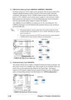
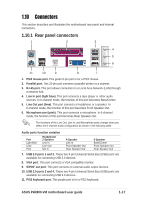
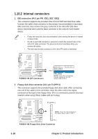
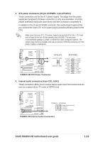
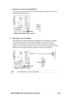
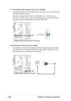
3. ATX power connectors (20-pin ATXPWR1, 4-pin ATX12V1) These connectors are for the ATX power supply. The plugs from the power supply are designed to fit these connectors in only one orientation. Find the proper orientation and push down firmly until the connectors completely fit. In addition to the 20-pin ATXPWR connector, this motherboard requires that you connect the 4-pin ATX +12V power plug to provide sufficient power to the CPU. Make sure that your ATX 12V power supply can provide 8A on the +12V lead and at least 1A on the +5-volt standby lead (+5VSB). The minimum recommended wattage is 230W, or 300W for a fully configured system. The system may become unstable and may experience difficulty powering up if the power supply is inadequate. P4R800-VM ATX12V1 +12V DC GND +12V DC GND P4R800-VM ATX Power Connector ATXPWR1 +12.0VDC +5VSB PWR_OK COM +5.0VDC COM +5.0VDC COM +3.3VDC +3.3VDC +5.0VDC +5.0VDC -5.0VDC COM COM COM PS_ON# COM -12.0VDC +3.3VDC 4. Internal audio connectors (4-pin CD1, AUX1) These connectors allow you to receive stereo audio input from sound sources such as a optical drive, TV tuner, or MPEG card. P4R800-VM CD(Black) AUX(White) Right Audio Channel Ground Ground Left Audio Channel P4R800-VM Internal Audio Connectors ASUS P4R800-VM motherboard user guide 1-19
-
 1
1 -
2
-
3
-
4
-
5
-
6
-
7
-
8
-
9
-
10
-
11
-
12
-
13
-
14
-
15
-
16
-
17
-
18
-
19
-
20
-
21
-
22
-
23
-
 24
24 -
 25
25 -
 26
26 -
 27
27 -
 28
28 -
 29
29 -
 30
30 -
 31
31 -
 32
32 -
 33
33 -
 34
34 -
35
-
36
-
37
-
38
-
39
-
40
-
41
-
42
-
43
-
44
-
45
-
46
-
47
-
48
-
49
-
50
-
51
-
52
-
53
-
54
-
55
-
56
-
57
-
58
-
59
-
60
-
61
-
62
-
63
-
64
 |
 |
