Asus p4r800vm Motherboard DIY Troubleshooting Guide - Page 33
System panel connector 10-1 pin F_PANEL1, Power LED 2-pin PWR_LED, Power LED Lead 3-1 pin PLED1
 |
View all Asus p4r800vm manuals
Add to My Manuals
Save this manual to your list of manuals |
Page 33 highlights
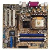
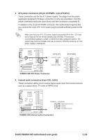
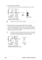
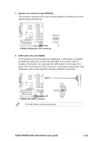
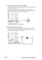
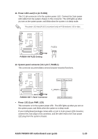
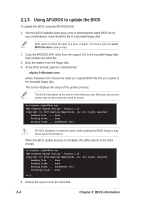
11. Power LED Lead (3-1 pin PLED1) This 3-1 pin connector is for the system power LED. Connect the 3-pin power LED cable from the system chassis to this connector. The LED lights up when you turn on the system power, and blinks when the system is in sleep mode. The power LED lead (PLED1) is present only on PCB versions 1.03 or later. P4R800-VM P4R800-VM PLED Setting PLED1 1 PLED+ NC PLED- 12. System panel connector (10-1 pin F_PANEL1) This connector accommodates several chassis-mounted functions. P4R800-VM Power LED+ Power LEDPower Switch Ground Power LED Power Switch F_PANEL1 IDE LED+ IDE LED- Ground Reset P4R800-VM F_Panel Connector IDE_LED Reset Switch • Power LED (2-pin PWR_LED) This connector is for the system power LED. The LED lights up when you turn on the system power, and blinks when the system is in sleep mode. If your motherboard package comes with a 2-pin to 3-pin power LED converter, connect the 2-pin plug to this connector, and the other end to the 3-pin power LED plug from the system chassis. ASUS P4R800-VM motherboard user guide 1-23
-
 1
1 -
2
-
3
-
4
-
5
-
6
-
7
-
8
-
9
-
10
-
11
-
12
-
13
-
14
-
15
-
16
-
17
-
18
-
19
-
20
-
21
-
22
-
23
-
24
-
25
-
26
-
27
-
 28
28 -
 29
29 -
 30
30 -
 31
31 -
 32
32 -
 33
33 -
 34
34 -
 35
35 -
 36
36 -
 37
37 -
 38
38 -
39
-
40
-
41
-
42
-
43
-
44
-
45
-
46
-
47
-
48
-
49
-
50
-
51
-
52
-
53
-
54
-
55
-
56
-
57
-
58
-
59
-
60
-
61
-
62
-
63
-
64
 |
 |