Audiovox MMD70 Installation Manual - Page 10
AV2 Input VCP, Game, DVD, etc
 |
UPC - 044476017230
View all Audiovox MMD70 manuals
Add to My Manuals
Save this manual to your list of manuals |
Page 10 highlights
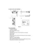
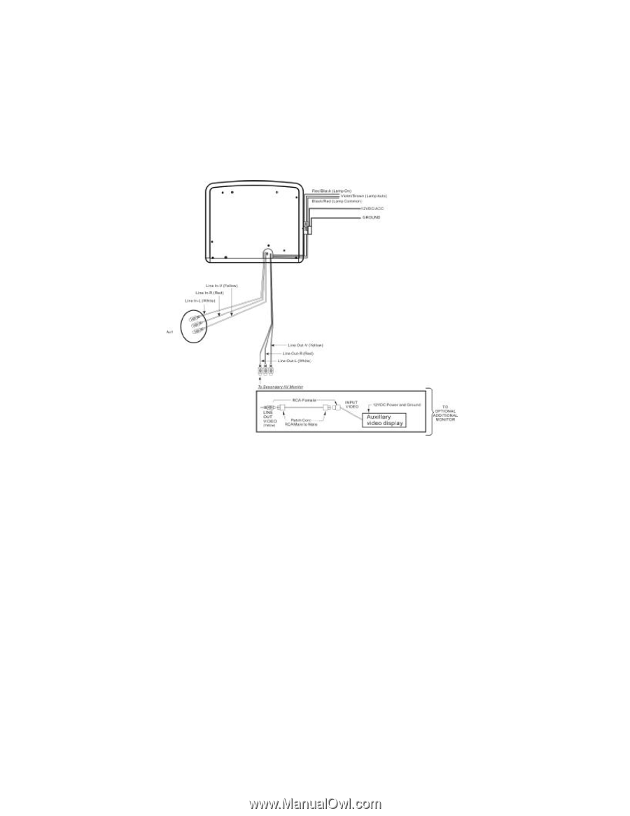
MMD70 (RED) (BLACK) Figure 3 1) Make the connections to the vehicle with the 5 pin wiring harness. 2) Connect the 5 pin harness to the mating connector on the Video Monitor. 3) Connect power harness to vehicle's electrical system by tapping into an accessory hot line. 4) Verify all functions of the system before final mounting of the finished assembly. NOTE: A VCP or other A/V Component can be connected to the video monitor system using an RCA A/V cable. This second harness would plug into the AV1 inputs or AUX jack. A/V Source Definitions : 1 = Built-in DVD 2 = AV1 input ( VCP, Game, DVD, etc ) 3 = AV2 Input ( VCP, Game, DVD, etc ) 10
-
 1
1 -
2
-
3
-
4
-
 5
5 -
 6
6 -
 7
7 -
 8
8 -
 9
9 -
 10
10 -
 11
11 -
 12
12 -
 13
13 -
 14
14 -
 15
15 -
16
-
17
-
18
-
19
-
20
-
21
-
22
-
23
-
24
-
25
-
26
-
27
-
28
-
29
-
30
-
31
 |
 |
10
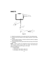
1)
Make the connections to the vehicle with the 5 pin wiring harness.
2)
Connect the 5 pin harness to the mating connector on the Video
Monitor.
3)
Connect power harness to vehicle's electrical system by tapping
into an accessory hot line.
4)
Verify all functions of the system before final mounting of the finished
assembly.
NOTE:
A VCP or other A/V Component can be connected to the
video monitor system using an RCA A/V cable. This second har-
ness would plug into the AV1 inputs or AUX jack.
A/V Source Definitions :
1 = Built-in DVD
2 =AV1 input ( VCP, Game, DVD, etc )
3 =AV2 Input ( VCP, Game, DVD, etc )
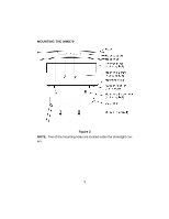
Figure 3
MMD70
(
RED
)
(
BLACK
)