Audiovox MMD70 Installation Manual - Page 13
E. Controls, Indicators, and Connectors,
 |
UPC - 044476017230
View all Audiovox MMD70 manuals
Add to My Manuals
Save this manual to your list of manuals |
Page 13 highlights
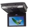
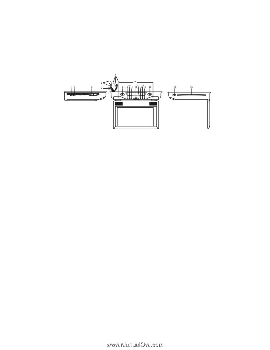
E. Controls, Indicators, and Connectors 1. Unit View (Refer to Figure 5) Figure 6 1) AV 2 In 2) Headphone Jack 3) Auto/Off/On(Dome Light) 4) Power and Dome Light Connector 5) AV1 RCA Jacks(red,white,yellow) 6) AV Output RCA Jacks (red,white,yellow) 7) Dome Lights 8) Power Button 9) Fast Reverse Button 10) STOP Button 11) Fast Forward Button 12) Monitor Open Button 13) IR Sensor and IR Transmitter for Wireless Headphones 14) Volume 15) Picture 16) Volume + 17) Play button 18) Eject button 19) Disc Insertion Slot 13
-
 1
1 -
2
-
3
-
4
-
5
-
6
-
7
-
 8
8 -
 9
9 -
 10
10 -
 11
11 -
 12
12 -
 13
13 -
 14
14 -
 15
15 -
 16
16 -
 17
17 -
 18
18 -
19
-
20
-
21
-
22
-
23
-
24
-
25
-
26
-
27
-
28
-
29
-
30
-
31
 |
 |
13
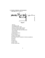
E. Controls, Indicators, and Connectors
1. Unit View
(Refer to Figure 5)
Figure 6
1) AV 2 In
2) Headphone Jack
3) Auto/Off/On(Dome Light)
4) Power and Dome Light Connector
5) AV1 RCA Jacks(red,white,yellow)
6) AV Output RCA Jacks (red,white,yellow)
7) Dome Lights
8) Power Button
9) Fast Reverse Button
10) STOP Button
11) Fast Forward Button
12) Monitor Open Button
13) IR Sensor and IR Transmitter for Wireless Headphones
14) Volume -
15) Picture
16) Volume +
17) Play button
18) Eject
button
19) Disc Insertion Slot