Axis Communications 291 1U 291 1U Video Server Rack - Guide d'installation - Page 7
AXIS blade video servers, AXIS Video Server Rack Installation Guide, ENGLISH
 |
View all Axis Communications 291 1U manuals
Add to My Manuals
Save this manual to your list of manuals |
Page 7 highlights
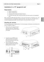
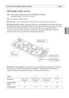
AXIS Video Server Rack Installation Guide Page 7 AXIS blade video servers S/N - (serial number) is identical to the unit's MAC/Ethernet address, e.g. 00408C1A2B3C = 00-40-8C-1A-2B-3C. P/N - is the product's model number. Bus Connector - This is the physical interface to the I/O terminal connector on the rack. DIP Switches (4-port models) - Each video input has a corresponding line termination DIP switch. Axis blade video servers are supplied with the line termination enabled for each input; i.e. with the DIP switches set to ON (down position). To connect the video server in parallel with other equipment, disable the input termination by setting the corresponding DIP switch to OFF (up position). Failure to do so may affect the image quality negatively. DIP Switches ENGLISH Bus Connector 4 Video inputs S/N & P/N label DIP Switches (1-port models) - These models can accommodate either composite or Y/C video. The type to use is determined by the DIP switch settings. 1-port AXIS blade video servers are supplied configured for composite video input, as shown in the table below. Switch Description Composite video input Y/C video input 1 75 ohm video in termination on 2 3 75 ohm video out termination off Connects video in and video out on on on off 4 Not used n/a n/a
-
 1
1 -
 2
2 -
 3
3 -
 4
4 -
 5
5 -
 6
6 -
 7
7 -
 8
8 -
 9
9 -
 10
10 -
 11
11 -
 12
12 -
13
-
14
-
15
-
16
-
17
-
18
-
19
-
20
-
21
-
22
-
23
-
24
-
25
-
26
-
27
-
28
-
29
-
30
-
31
-
32
-
33
-
34
-
35
-
36
-
37
-
38
-
39
-
40
-
41
-
42
-
43
-
44
-
45
-
46
-
47
-
48
-
49
-
50
-
51
 |
 |
