Axis Communications 291 1U 291 1U Video Server Rack - Guide d'installation - Page 8
The I/O Terminal connector, Mounting AXIS blade video servers
 |
View all Axis Communications 291 1U manuals
Add to My Manuals
Save this manual to your list of manuals |
Page 8 highlights
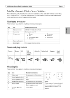
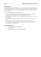
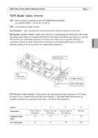
Page 8 AXIS Video Server Rack Installation Guide Mounting AXIS blade video servers The AXIS Video Server Rack can accommodate 3 Axis blade video servers. The slots for these are numbered 1-3 from left to right, as seen from the front. The I/O connectors for each slot on the rear panel are also numbered. 1. Remove a front panel cover from the slot in which the video server will be mounted. This is done by unfastening the screw on each side of the cover. 2. Slide the video server into place, using the guides as an aid. The dip switch for setting the line termination should be visible on the top edge. 3. Fix the video server in place, using the screws from the front panel cover. Note: Leaving an empty slot on the AXIS Video Server Rack open is not permitted. Front panel covers must be used on all empty slots. The I/O Terminal connector The AXIS Video Server Rack server provides an I/O terminal connector for each Axis blade video server (see illustration on page 4). This is used for connecting external equipment, in applications for e.g. motion detection, event triggering, time lapse recording, alarm notification via email, image storage to FTP locations, etc.
-
 1
1 -
2
-
 3
3 -
 4
4 -
 5
5 -
 6
6 -
 7
7 -
 8
8 -
 9
9 -
 10
10 -
 11
11 -
 12
12 -
 13
13 -
14
-
15
-
16
-
17
-
18
-
19
-
20
-
21
-
22
-
23
-
24
-
25
-
26
-
27
-
28
-
29
-
30
-
31
-
32
-
33
-
34
-
35
-
36
-
37
-
38
-
39
-
40
-
41
-
42
-
43
-
44
-
45
-
46
-
47
-
48
-
49
-
50
-
51
 |
 |
