Axis Communications 291 1U 291 1U Video Server Rack - Guide d'installation - Page 9
Connector interfaces, Connector pinout
 |
View all Axis Communications 291 1U manuals
Add to My Manuals
Save this manual to your list of manuals |
Page 9 highlights
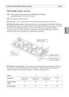
AXIS Video Server Rack Installation Guide Page 9 ENGLISH Connector interfaces The interfaces available via the 12-pin I/O terminal connector are as follows: • 4 Digital inputs - used for e.g. a pushbutton. If the button is pressed, the state changes and the input will be active (shown under Event Configuration > Port Status). (AXIS 241Q Blade, AXIS 241S Blade, AXIS 243Q, AXIS 240Q) • 4 Transistor outputs - for e.g. alarm devices that can be activated from Output buttons on the Live View page, or as an action to an Event Type. The output will show as active (in Event Configuration > Port Status) if the device is activated. • 10 configurable I/O connectors (AXIS Q7406) • RS-485 interface, for e.g. Pan/Tilt/Zoom devices (see www.axis.com for drivers) • Auxiliary power Connector pinout Pin AXIS Q7406 1 +12V out, 100mA 2 GND 3 Channel 1, Configurable I/O 1 4 Channel 2, Configurable I/O 1 5 Channel 3, Configurable I/O 1 6 Channel 4, Configurable I/O 1 7 Channel 5, Configurable I/O 1 8 Channel 6, Configurable I/O 2 9 Channel 1, Configurable I/O 2 10 Channel 2, Configurable I/O 2 11 Channel 1, RS485A 12 Channel 1, RS485B AXIS 243Q +12V out, 100mA GND Channel 1, Input 1 Channel 2, Input 1 Channel 3, Input 1 Channel 4, Input 1 Channel 1, Input 1 Channel 2, Input 1 Channel 3, Input 1 Channel 4, Input 1 Channel 1, RS485A Channel 1, RS485B AXIS 241Q Blade, AXIS 241S Blade, AXIS 240Q +12V out, 100mA GND Input1 Input 2 Input 3 Input 4 Output1 Output2 Output3 Output4 RS485A RS485B To connect input/output devices to the I/O terminal connector: 1. Referring to the table above, loosen the corresponding screw on top of the pin on the green connector block. 2. Push the cable into the connector block and secure it by fastening the screw. 3. Once all devices are connected, push the connector block into the terminal connector on the rear panel of the AXIS Video Server Rack. For compatible replacement connectors, contact http://www.phoenixcontact.com, quoting: MC1.5/ 12-ST-3.81 (art no 1803675).
-
 1
1 -
2
-
3
-
 4
4 -
 5
5 -
 6
6 -
 7
7 -
 8
8 -
 9
9 -
 10
10 -
 11
11 -
 12
12 -
 13
13 -
 14
14 -
15
-
16
-
17
-
18
-
19
-
20
-
21
-
22
-
23
-
24
-
25
-
26
-
27
-
28
-
29
-
30
-
31
-
32
-
33
-
34
-
35
-
36
-
37
-
38
-
39
-
40
-
41
-
42
-
43
-
44
-
45
-
46
-
47
-
48
-
49
-
50
-
51
 |
 |
