Behringer DEQ1024 Manual - Page 5
Deactivating the FEEDBACK DESTROYER - ultragraph digital graphic equalizer
 |
View all Behringer DEQ1024 manuals
Add to My Manuals
Save this manual to your list of manuals |
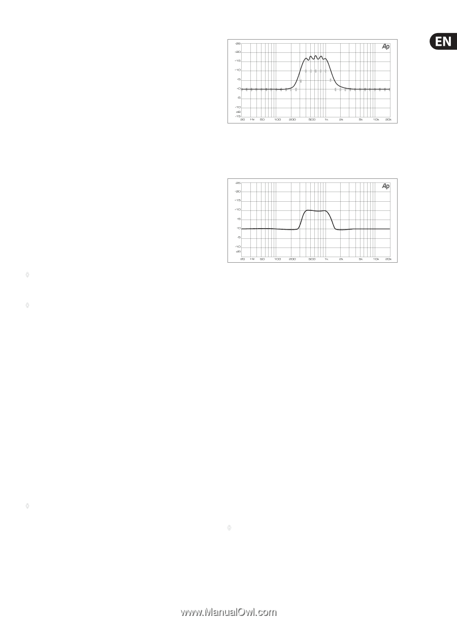
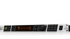
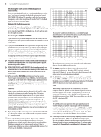
Page 5 highlights
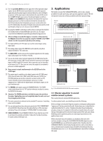
5 ULTRAGRAPH DIGITAL DEQ1024 Deactivating the search function (feedback suppression remains active): If you now press the ON/OFF switch for a second time, the feedback analysis stops. Those frequencies emitting feedback will continue being lowered (RESET (HOLD) LED is still on). This procedure is well suited for stationary microphones, such as drum microphones. To start the "hunt" for feedback again, hit the ON/OFF switch once again. Displaying the feedback frequencies: If you briefly (for approx. 2 seconds) depress the RESET (HOLD) switch, the feedback frequencies that the DEQ1024 was able to find will be indicated on the respective fader LEDs. If no feedback occurs, the LEDs will stop being lit up for roughly 2 seconds. Deactivating the FEEDBACK DESTROYER: If you hold the RESET (HOLD) switch depressed for a few seconds, the filter settings are reset (RESET (HOLD) LED dies out) and the FEEDBACK DESTROYER is deactivated. (4) If you press the FB INDICATOR switch (green switch LED lights up), the FBQ feedback detection system is activated. The frequency (or the frequencies) that cause feedback are now shown in the form of a brightly shining fader LED. All other LEDs are dimmed. Simply lower somewhat the pertinent frequency range until feedback is no longer present and the LED dies out. By displaying the intensity of individual frequency ranges, the feedback recognition system also functions as an audio analyzer. ◊ Please keep in mind that the FB INDICATOR only shows the intensity of the individual frequency bands. Not every frequency that is present automatically causes feedback. ◊ FEEDBACK DESTROYER and FB INDICATOR function independently from one another and can be activated simultaneously. Please bear in mind: when in 96-kHz mode, FEEDBACK DESTROYER and FB INDICATOR are not available! (5) When you keep the PINK NOISE switch depressed for a few seconds, the internal pink noise generator of your DEQ1024 is activated (red switch LED lights up) and the volume level of the test signal is gradually increased as long as the switch remains depressed (the level is shown on LEVEL METER (13)). Briefly pressing the PINK NOISE switch once again deactivates the function. PINK NOISE Room resonance and the transmission characteristics of your P.A. system naturally lift certain frequencies while lowering others. Pink noise is a neutral signal that can be played back over the P.A. system in order to measure these room characteristics. One such measurement of the frequency response with a special measurement microphone (e. g. BEHRINGER ECM8000) coupled to a real-time analyzer (integrated in the BEHRINGER ULTRACURVE PRO DEQ2496) delivers the foundation for setting up the equalizer. Boosted frequencies can be lowered by means of your equalizer, while frequencies that are too weak can be boosted, and a nearly linear playback is achieved. ◊ Try to orient yourself on a frequency whose signal level lies in the 0 dB to -3 dB range in order to avoid overdriving the equipment connected (e. g. amp, crossover). (6) In the world of ordinary graphic equalizers, there is always a difference between the adjusted curve and the resulting frequency response. This phenomenon is simply caused by the construction of such equalizers. This difference depends on the frequency and its cut/boost. Near-by frequency bands influence one another, whereby individual instances of cut or boost can also be added up to one another. Fig. 2.2: Graphic equalizer without frequency response correction This occurrence can be corrected by means of a specially developed algorithm utilized in the ULTRAGRAPH DIGITAL DEQ1024. Simply press the TRUE CURVE switch (green switch LED lights up). Fig. 2.3: Graphic equalizer with frequency response correction (TRUE CURVE) The resulting frequency response now corresponds exactly to the settings that you adjusted with the graphic equalizer. (7) The BYPASS switch lets you directly compare the processed and unprocessed audio program. When the BYPASS function is activated (red switch LED lights up), the input of the unit is directly forwarded to the output so you can monitor the unprocessed signal. (8) The DYNAMICS section of the DEQ1024 consists of a GATE and a LIMITER. Use the GATE and LIMITER controls to determine the threshold. When the threshold is exceeded (LIMITER) or when the signal falls below the threshold (GATE), the dynamic processors starts affecting the signal. GATE When the input signal falls below the threshold value, the signal is completely faded out. Tape hiss, crosstalk or disturbing noise can thus be effectively removed from the signal. The yellow GATE LED in the METER section (see (13)) lights up as soon as the GATE closes. The range of the threshold lies between -60 and -10 dB. When turned all the way to the left, the GATE is deactivated (OFF). LIMITER The LIMITER protects your equipment from signal peaks that could for example damage your speakers. Output signal levels that exceed the selected threshold value are limited, and the red LIMITER LED in the METER section (see (13)) lights up. By reducing signal dynamics, a more expressive sound is achieved. The threshold range lies between -6 and +9 dB. When turned all the way to the right, the LIMITER is deactivated (OFF). ◊ Please keep in mind that boosting many frequency bands also increases the output signal level. In this case, the limiter is activated sooner. You can avoid this by achieving signal correction not only by boosting frequency bands but by also lowering signal levels. To achieve creative sound effects, the peak limiter can deliberately be driven to its limits.
-
 1
1 -
 2
2 -
 3
3 -
 4
4 -
 5
5 -
 6
6 -
 7
7 -
 8
8 -
 9
9 -
 10
10 -
 11
11 -
12
 |
 |