Behringer DEQ1024 Manual - Page 7
Applications - ultragraph digital equalizer
 |
View all Behringer DEQ1024 manuals
Add to My Manuals
Save this manual to your list of manuals |
Page 7 highlights
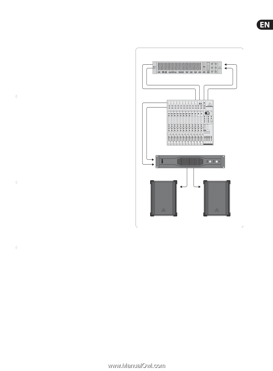
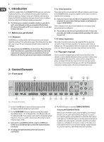
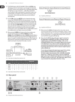
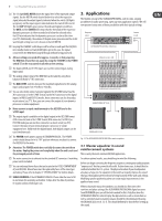
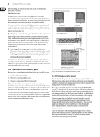
7 ULTRAGRAPH DIGITAL DEQ1024 (13) The 12-digit LEVEL METER shows the signal level of the input and output signals. Use the METER switch located below it to select the respective signal, whereby the output signal is indicated when the switch LED lights up (green), and the input signal is indicated when the switch LED is not lit. The red CLIP LED lights up as soon as the indicated signal is overdriven. The GATE and the LIMITER LED shows that the threshold of the respective dynamics processors is either exceeded or is below the selected value; the LED also indicates that the dynamics processor is active at this time (see (8)). Additionally, the volume of the pink noise generator and the 24-bit word length setting (see (12)) is shown on the LED METER. 3. Applications The flexible concept of the ULTRAGRAPH DIGITAL, with its wide-ranging possibilities for audio processing, opens up many application options. We will now present to you some of those possibilities with their typical settings. Outputs L & R Inputs L & R (14) Keeping the STANDBY switch depressed for a few seconds puts the DEQ1024 into standby mode (red switch LED lights up). In this case, the signal connected to the DEQ1024 is looped through without being processed. ULTRAGRAPH DIGITAL DEQ1024 ◊ All new settings are saved after approx. 2 seconds, so that powering the DEQ1024 off and then on again (by using the STANDBY or the POWER switch (20) on the rear panel) recalls the current settings. Main Inserts L & R (15) The balanced XLR and 1/4" TRS inputs are used for connecting an analog input signal. (16) The analog output signal of the DEQ1024 can be taken by using these balanced XLR and 1/4" TRS connectors. (17) The MAX. LEVEL switches increase the maximum signal level on the analog inputs and outputs from +12 dBu to +22 dBu. (18) You can selectively connect an input signal in the AES/EBU format (via the XLR connector) or in the S/PDIF format (via the RCA connector) to the digital inputs. In PRE EQ and POST EQ modes, these connectors can also be used as insert returns (see (12)). Here, you can connect the output of your dynamics processor or similar equipment. EURORACK UB2442FX PRO EUROPOWER EP1500 ◊ Never connect a signal simultaneously to the AES/EBU and to the S/PDIF input. (19) The output signal is available on the digital output in the AES/EBU format (XLR connector) and in the S/PDIF format (RCA connector). In PRE EQ or POST EQ mode you can use these connectors as insert sends (see (11)). Connect the input of your external dynamics processor or similar equipment here. Unlike with the digital inputs, both digital outputs can be used simultaneously. EUROLIVE B1520 (20) The POWER switch powers up your ULTRAGRAPH DIGITAL. The POWER switch should always be in its "Off" position when you are about to connect the DEQ1024 to the mains. ◊ Attention: The POWER switch does not fully disconnect the unit from the mains. Unplug the power cord completely when the unit is not used for prolonged periods of time. Fig. 3.1: The ULTRAGRAPH DIGITAL DEQ1024 as master equalizer 3.1 Master equalizer in sound reinforcement systems This is surely the most common DEQ1024 application. (21) The mains connection is achieved via the standard IEC connector. A matching power cord is included. (22) You can exchange blown fuses that are located in the FUSES COMPARTMENT of your DEQ1024. Blown fuses must be replaced by fuses of the same type and rating. Please refer to chapter 5 "SPECIFICATIONS" for further details. (23) SERIAL NUMBER of the ULTRAGRAPH DIGITAL. Please take the time to fill in and return the warranty card within 14 days after the date of purchase. Or register online at behringer.com. To achieve optimal results, you should keep in mind the following: Before you begin correcting the frequency response, running your audio program "unprocessed" first has proved itself useful. If distortion occurs, it should first be confronted within the P.A. system. The physical location of your loudspeakers also plays a huge role. No equalizer in the world can majorly improve the sound that was thoroughly wattered down by being bounced off the walls and ceilings. Modifying speaker positioning alone can create major improvements in the quality of your sound. When using multi-way active speakers, you should also first correct the run-time and phase settings (the ULTRADRIVE PRO DCX2496 digital crossover from BEHRINGER gives you all the tools needed for this). Only then does the ULTRAGRAPH DIGITAL come into play. Background noise such as mains hum as well as extremely narrow-band resonance should first be eliminated by using the DEQ1024 (also see ch. 3.2.1). This should definitely be done before setting up the sound.
-
 1
1 -
 2
2 -
 3
3 -
 4
4 -
 5
5 -
 6
6 -
 7
7 -
 8
8 -
 9
9 -
 10
10 -
 11
11 -
 12
12
 |
 |