Behringer DEQ1024 Manual - Page 6
Rear panel - ultragraph digital
 |
View all Behringer DEQ1024 manuals
Add to My Manuals
Save this manual to your list of manuals |
Page 6 highlights
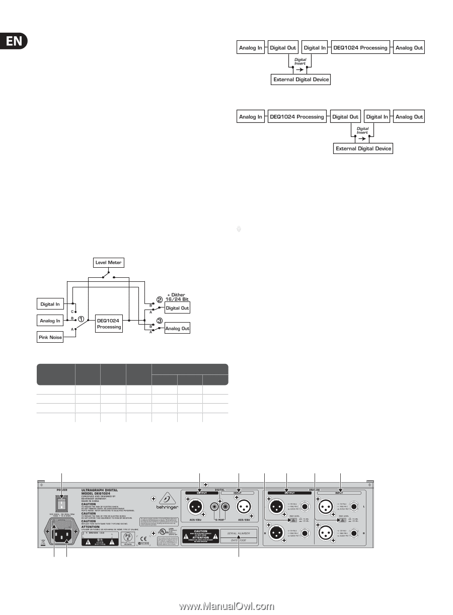
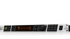
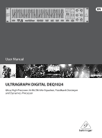
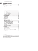
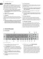
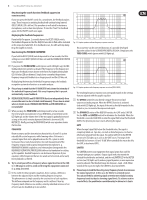
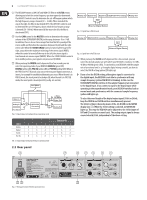
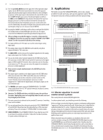
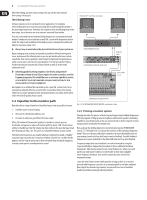
6 ULTRAGRAPH DIGITAL DEQ1024 (9) The DEQ1024 features a LOW CUT and HIGH CUT filter in its FILTER section, allowing you to limit the entire frequency spectrum upward or downward. The HIGH CUT control is used to determine the cut-off frequency above which the high frequency range is lowered (2.5 - 16 kHz). When turned all the way to the right, the filter is deactivated (OFF). The LOW CUT control is used to determine the cut-off frequency above which the low frequency range is lowered (20 - 160 Hz). When turned all the way to the left, the filter is deactivated (OFF). (10) Use the GAIN control in the MASTER section to determine the output volume of the ULTRAGRAPH DIGITAL in the range between -9 to +9 dB. In addition, there is also a stereo imager function that lets you adjust the stereo width and therefore the separation between the left and the right stereo side. When the STEREO IMAGE control is turned all the way to the right, you achieve the maximum widening of the stereo signal (WIDE); when the control is turned all the way to the left, the stereo signal is transformed into a mono signal (MONO). When the STEREO IMAGE control is in its middle position, your signal is not processed (STEREO). (11) When you keep the CONFIG switch depressed for a few seconds, you can select the operating mode of your DEQ1024: ANALOG (green LED), DIGITAL (yellow LED), PRE EQ (yellow LED) or POST EQ (yellow LED). When in the PRE EQ or POST EQ mode, you can use the rear panel digital connectors as inserts, for example for an additional dynamics processor. When the unit is in PRE EQ mode, the insert point is located pre EQ; when the unit is in POST EQ mode, the insert point is located post EQ (see fig. 2.5 and 2.6). Fig. 2.4: Input/output wiring depending on operating mode Fig. 2.5: Signal flow in PRE EQ mode Fig. 2.6: Signal flow in POST EQ mode (12) When you keep the CLOCK switch depressed for a few seconds, you can select the desired sample rate with which your DEQ1024 is working: 44.1 kHz, 48 kHz or 96 kHz (green LEDs). To synchronise your DEQ1024 with the sample rate of an external unit (e. g. through a digital mixing console), you have to select the DIG IN setting (yellow LED lights up). ◊ If you select the DIG IN setting, although no signal is connected to the digital input, the DEQ1024 is not able to synchronise with any sample frequency (yellow DIG IN LED is blinking). In this case the ULTRAGRAPH DIGITAL switches to the sample frequency last connected to the digital input. If you connect a signal to the digital input while operating in the unsynchronised mode, your DEQ1024 switches back to normal mode and synchronises with the connected sample frequency (yellow LED lights up). To select the word length of the digital output signal (16 bit or 24 bit), keep the CONFIG and CLOCK switches simultaneously pressed. The 24-bit setting is shown by means of the -24 dB LEDs in the METER display (see (13)). When the 16-bit setting is selected, no METER LED lights up. This way, the DEQ1024 can be adjusted to the 16-bit inputs of DAT and CD recorders or sound cards. The analog output signal is always converted with 24 bit, independent of the above setting. Pink Noise ON CONFIG 1 2 3 1 2 3 Analog B A A A A A Digital C A A A A A Pre EQ C B A A B A Post EQ B A B A A B Tab. 2.1: Input/output wiring depending on operating mode 2.2 Rear panel (20) (19) (18) (17) (16) (17) (15) (22) (21) (23) Fig. 2.7: Rear panel control elements and connectors
-
 1
1 -
 2
2 -
 3
3 -
 4
4 -
 5
5 -
 6
6 -
 7
7 -
 8
8 -
 9
9 -
 10
10 -
 11
11 -
 12
12
 |
 |