Belkin F1DM208T User Manual - Page 8
Unit Display Diagrams
 |
View all Belkin F1DM208T manuals
Add to My Manuals
Save this manual to your list of manuals |
Page 8 highlights
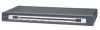
OVERVIEW UNIT DISPLAY DIAGRAMS Front View of the MATRIX2 Console A 7-segment LED for selected BANK identification Console B 7-segment LED for selected BANK identification Console A LED for selected port identification Console B LED for selected port identification Console A Manual BANK scroll buttons Console A direct-access port selector Console B direct-access port selector Console B Manual BANK scroll buttons Back View of the MATRIX2 BANK DIP switch (may be located on the side in some models) Console B VGA Daisy-chain Input port and PS/2 connections Console A VGA and PS/2 connections DC power jack Daisy-chain Output port Flash upgrade port FLASH DIP switch (may be located on the side in some models) 6 DB25 CPU connector
-
 1
1 -
2
-
 3
3 -
 4
4 -
 5
5 -
 6
6 -
 7
7 -
 8
8 -
 9
9 -
 10
10 -
 11
11 -
 12
12 -
 13
13 -
14
-
15
-
16
-
17
-
18
-
19
-
20
-
21
-
22
-
23
-
24
-
25
-
26
-
27
-
28
-
29
-
30
-
31
-
32
-
33
-
34
-
35
-
36
-
37
-
38
-
39
-
40
 |
 |

6
OVERVIEW
UNIT DISPLAY DIAGRAMS
Front View of the MATRIX2
Back View of the MATRIX2
Console B
direct-access
port selector
Console A
Manual BANK
scroll buttons
Console A
7-segment LED for selected
BANK identification
Console B LED for
selected port
identification
DC power
jack
BANK DIP switch (may
be located on the side
in some models)
FLASH DIP switch
(may be located on the
side in some models)
Flash upgrade port
DB25 CPU
connector
Daisy-chain
Output port
Daisy-chain
Input port
Console B
Manual BANK
scroll buttons
Console B
7-segment LED for selected
BANK identification
Console A LED for
selected port
identification
Console A
direct-access
port selector
Console B VGA
and PS/2
connections
Console A VGA
and PS/2
connections