Biostar I945P-A7 I945P-A7 v1.x user's manual - Page 17
Headers & Jumpers Setup - atx
 |
View all Biostar I945P-A7 manuals
Add to My Manuals
Save this manual to your list of manuals |
Page 17 highlights
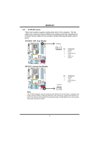
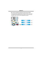
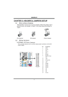
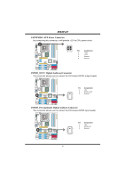
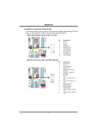
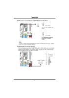
I945P-A7 CHAPTER 3: HEADERS & JUMPERS SETUP 3.1 HOW TO SETUP JUMPERS The illustration shows how to set up jumpers. When the jumper cap is placed on pins, the jumper is "close", if not, that means the jumper is "open". Pin opened Pin closed Pin1-2 closed 3.2 DETAIL SETTINGS JATXPWR1: ATX Power Connector This connector allows user to connect 24-pin power connector on the ATX power supply. COM1 Pin Assignment 1 +3.3V 2 +3.3V 3 Ground 4 +5V 5 Ground 6 +5V 13 1 7 Ground 8 PW_OK 9 Standby Voltage +5V 10 +12V 11 +12V 12 2 x 12 Detect 13 +3.3V 14 -12V 15 Ground Codec 16 PS_ON 17 Ground 24 12 18 Ground 19 Ground 20 -5V 21 +5V 22 +5V 23 +5V 24 Ground 15
-
 1
1 -
2
-
3
-
4
-
5
-
6
-
7
-
8
-
9
-
10
-
11
-
 12
12 -
 13
13 -
 14
14 -
 15
15 -
 16
16 -
 17
17 -
 18
18 -
 19
19 -
 20
20 -
 21
21 -
 22
22 -
23
-
24
-
25
-
26
-
27
-
28
-
29
-
30
-
31
-
32
-
33
-
34
-
35
-
36
-
37
-
38
 |
 |

I945P-A7
15
CHAPTER 3: HEADERS & JUMPERS SETUP
3.1
H
OW TO
S
ETUP
J
UMPERS
The illustration shows how to set up jumpers. When the jumper cap is
placed on pins, the jumper is “close”, if not, that means the jumper is
“open”.
Pin opened
Pin closed
Pin1-2 closed
3.2
D
ETAIL
S
ETTINGS
JATXPWR1: ATX Power Connector
This connector allows user to connect 24-pin power connector on the ATX
power supply.
Pin
Assignment
1
+3.3V
2
+3.3V
3
Ground
4
+5V
5
Ground
6
+5V
7
Ground
8
PW_OK
9
Standby Voltage
+5V
10
+12V
11
+12V
12
2 x 12 Detect
13
+3.3V
14
-12V
15
Ground
16
PS_ON
17
Ground
18
Ground
19
Ground
20
-5V
21
+5V
22
+5V
23
+5V
13
1
24
12
Codec
C
O
M
1
24
Ground