Biostar I945P-A7 I945P-A7 v1.x user's manual - Page 24
JCMOS1: Clear CMOS Header, Clear CMOS Procedures, JCI1: Chassis Open Header
 |
View all Biostar I945P-A7 manuals
Add to My Manuals
Save this manual to your list of manuals |
Page 24 highlights
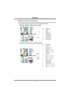
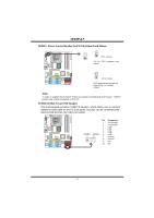
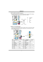
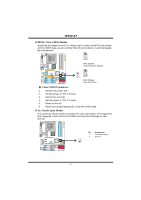
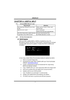
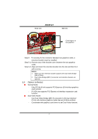
I945P-A7 JCMOS1: Clear CMOS Header By placing the jumper on pin2-3, it allows user to restore the BIOS safe setting and the CMOS data, please carefully follow the procedures to avoid damaging the motherboard. 1 COM1 3 Pin 1-2 Close: Normal Operation (default). 1 1 3 Codec 3 Pin 2-3 Close: Clear CMOS data. ※ Clear CMOS Procedures: 1. Remove AC power line. 2. Set the jumper to "Pin 2-3 close". 3. Wait for five seconds. 4. Set the jumper to "Pin 1-2 close". 5. Power on the AC. 6. Reset your desired password or clear the CMOS data. JCI1: Chassis Open Header This connector allows system to monitor PC case open status. If the signal has been triggered, it will record to the CMOS and show the message on next boot-up. COM1 Pin Assignment 1 Case open signal 2 Ground 2 1 Codec 22
-
 1
1 -
2
-
3
-
4
-
5
-
6
-
7
-
8
-
9
-
10
-
11
-
12
-
13
-
14
-
15
-
16
-
17
-
18
-
 19
19 -
 20
20 -
 21
21 -
 22
22 -
 23
23 -
 24
24 -
 25
25 -
 26
26 -
 27
27 -
 28
28 -
 29
29 -
30
-
31
-
32
-
33
-
34
-
35
-
36
-
37
-
38
 |
 |
