Biostar I945P-A7 I945P-A7 v1.x user's manual - Page 23
SATA1~SATA4: Serial ATA Connectors, JPANEL1: Front Panel Header - specs
 |
View all Biostar I945P-A7 manuals
Add to My Manuals
Save this manual to your list of manuals |
Page 23 highlights
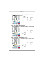
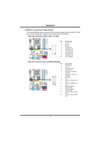
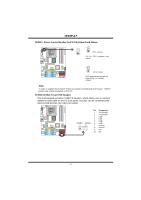
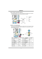
I945P-A7 SATA1~SATA4: Serial ATA Connectors The motherboard has a PCI to SATA Controller with 4 channels SATA interface, it satisfies the SATA 2.0 spec and with transfer rate of 3Gb/s. COM1 Pin Assignment 1 Ground SATA4 SATA3 2 TX+ 3 TX- 1 4 Ground 5 RX- 4 6 RX+ 7 Ground Codec 7 SATA2 SATA1 JPANEL1: Front Panel Header This 24-pin connector includes Power-on, Reset, HDD LED, Power LED, Sleep button, speaker and IrDA Connection. It allows user to connect the PC case's front panel switch functions. COM1 Codec Pin Assignment 1 +5V 3 N/A 5 N/A 7 Speaker 9 HDD LED (+) 11 HDD LED (-) 13 Ground 15 Reset control 17 N/A 19 N/A 21 +5V 23 IRTX 24 23 IR IR On/Off PWR_LED SLP ++ +- RST HLED SPK 21 Function Pin Assignment 2 Sleep control Speaker Connector 4 Ground 6 N/A 8 Power LED (+) Hard drive LED 10 Power LED (+) 12 Power LED (-) Reset button 14 Power button 16 Ground 18 Key IrDA Connector 20 Key 22 Ground 24 IRRX Function Sleep button N/A Power LED Power-on button IrDA Connector 21
-
 1
1 -
2
-
3
-
4
-
5
-
6
-
7
-
8
-
9
-
10
-
11
-
12
-
13
-
14
-
15
-
16
-
17
-
 18
18 -
 19
19 -
 20
20 -
 21
21 -
 22
22 -
 23
23 -
 24
24 -
 25
25 -
 26
26 -
 27
27 -
 28
28 -
29
-
30
-
31
-
32
-
33
-
34
-
35
-
36
-
37
-
38
 |
 |
