Biostar IDEQ N1 MANUAL - Page 26
J1394PWR1, optional, Power, Source, Header, JPANELl, Front, Panel
 |
View all Biostar IDEQ N1 manuals
Add to My Manuals
Save this manual to your list of manuals |
Page 26 highlights
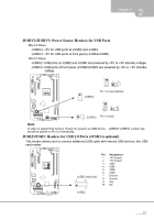
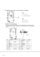
J1394PWR1 (optional): Power Source Header for 1394 Chip L_ _ELI-HI 3 Pin 1-2 Close +3.3V for 1394 chipset (Default) • 1 0 3 1 • 3 Pin 2-3 Close +3.3V SB for 1394 chipset. JPANELl: Front Panel Header This 24-pin connector includes Power-on, Reset, HDD LED, Power LED, Sleep button, speaker and IrDA Connection. It allows user to connect the PC cases front panel switch functions. L=J PWR_LED SLP On/Off 000 •00000 00 24 000 23 n n SPK RST HLED IR(optional) Pin Assignment 1 +5V 3 N/A 5 N/A 7 Speaker 9 HDD LED (+) 11 HDD LED (-) 13 Ground 15 Reset control 17 N/A 19 N/A 21 +5V 23 IRTX Function Pin 2 Speaker 4 Connector 6 8 Hard drive LED 10 12 Reset button 14 16 18 IrDA Connector 20 (optional) 22 24 Assignment Sleep control Ground N/A Power LED (+) Power LED (+) Power LED (-) Power button Ground N/A Key Ground IRRX Function Sleep button N/A Power LED Power-on button IrDA Connector (optional) 20
-
 1
1 -
2
-
3
-
4
-
5
-
6
-
7
-
8
-
9
-
10
-
11
-
12
-
13
-
14
-
15
-
16
-
17
-
18
-
19
-
20
-
 21
21 -
 22
22 -
 23
23 -
 24
24 -
 25
25 -
 26
26 -
 27
27 -
 28
28 -
 29
29 -
 30
30 -
 31
31 -
32
-
33
-
34
-
35
-
36
-
37
-
38
-
39
-
40
-
41
-
42
-
43
-
44
-
45
-
46
-
47
-
48
-
49
-
50
-
51
-
52
-
53
-
54
-
55
-
56
-
57
-
58
-
59
 |
 |
