Biostar M6VLQ M6VLQ user's manual - Page 24
Reset Button, Power LED Connector, HDD LED Hard Drive LED Connector, IrDA Infrared Connector, Sleep - driver
 |
View all Biostar M6VLQ manuals
Add to My Manuals
Save this manual to your list of manuals |
Page 24 highlights
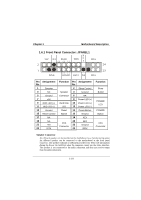
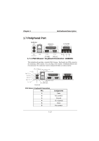
Chapter 1 Motherboard Description Reset Button This connector can be attached to a momentary SPST switch. This switch is usually open and when closed will cause the motherboard to reset and run the POST (Power On Self Test). Power LED Connector This connector can be attached to an LED on the front panel of a computer case. The LED will illuminate while the computer is powered on. HDD LED (Hard Drive LED Connector) This connector can be attached to an LED on the front panel of a computer case. The LED will flicker during disk activity. This disk activity only applies to those IDE drives directly attached to the system board. IrDA (Infrared Connector) This connector is used to attach to an infrared sensing device. After the IrDA interface is configured, connectionless data transfer to and from portable devices such as laptops, PDAs is possible. Sleep Button (Green Button) This connector is used to conserve energy by powering down the monitor and the hard disk when not in use. To configure this option, you need to connect a button from the front panel to this connector. Depressing the button will power down the monitor and hard drives until the system is invoked by any keyboard activity, mouse activity, modem activity or when the sleep button is depressed again. APM (Advanced Power Management) must be enabled in the system BIOS and the APM driver must be loaded. Power Button This connector can be attached to a front panel power switch. The switch must pull the Power Button pin to ground for at least 50 ms to signal the power supply to switch on or off. (The time required is due to internal debounce circuitry on the system board). At least two seconds must pass before the power supply will recognize another on/off signal. 1-19
-
 1
1 -
2
-
3
-
4
-
5
-
6
-
7
-
8
-
9
-
10
-
11
-
12
-
13
-
14
-
15
-
16
-
17
-
18
-
 19
19 -
 20
20 -
 21
21 -
 22
22 -
 23
23 -
 24
24 -
 25
25 -
 26
26 -
 27
27 -
 28
28 -
 29
29 -
30
-
31
-
32
-
33
-
34
-
35
-
36
-
37
-
38
-
39
-
40
-
41
-
42
-
43
-
44
-
45
-
46
-
47
-
48
-
49
-
50
-
51
-
52
-
53
-
54
-
55
-
56
-
57
-
58
-
59
-
60
-
61
-
62
-
63
-
64
-
65
-
66
-
67
-
68
-
69
-
70
-
71
-
72
-
73
 |
 |