Biostar TA790GXE Setup Manual - Page 21
On-Board LED Indicators, On-Board Buttons - memory
 |
View all Biostar TA790GXE manuals
Add to My Manuals
Save this manual to your list of manuals |
Page 21 highlights
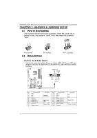
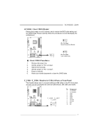
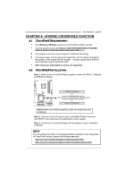
On-Board LED Indicators There are 6 LED indicators showing system status. TA790GXE 128M P H2 P H4 P H1 P H3 LE D_D2 LE D_D1 LED_D1 & LED_D2: Debug Indicators PH1 ~ PH4: Power Status Indicators Please refer to the tables below for specific messages: LED_D1 LED_D2 Message ON ON Normal ON OFF Memory Error OFF ON VGA Error OFF OFF Abnormal: CPU / Chipset error. PH1~PH4 ON OFF Phase Indicator Phase Active Phase Disable On-Board Buttons There are 2 on-board buttons. SW_PWR SW_RST: Reset button. SW_PWR: Power Switch button. SW_RST 19
-
 1
1 -
2
-
3
-
4
-
5
-
6
-
7
-
8
-
9
-
10
-
11
-
12
-
13
-
14
-
15
-
 16
16 -
 17
17 -
 18
18 -
 19
19 -
 20
20 -
 21
21 -
 22
22 -
 23
23 -
 24
24 -
 25
25 -
 26
26 -
27
-
28
-
29
-
30
-
31
-
32
-
33
-
34
-
35
-
36
-
37
-
38
-
39
-
40
-
41
-
42
-
43
-
44
-
45
-
46
-
47
-
48
-
49
-
50
-
51
-
52
-
53
-
54
-
55
-
56
-
57
-
58
-
59
-
60
-
61
-
62
-
63
-
64
-
65
-
66
-
67
-
68
-
69
 |
 |
TA790GXE 128M
19
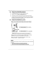
On-Board LED Indicators
There are 6 LED indicators showing system status.
LED_D1
LED_D2
PH2
PH1
PH4
PH3
LED_D1 & LED_D2:
Debug Indicators
PH1 ~ PH4:
Power Status Indicators
Please refer to the tables below for specific messages:
LED_D1
LED_D2
Message
ON
ON
Normal
ON
OFF
Memory Error
OFF
ON
VGA Error
OFF
OFF
Abnormal: CPU / Chipset error.
PH1~PH4
Phase Indicator
ON
Phase Active
OFF
Phase Disable
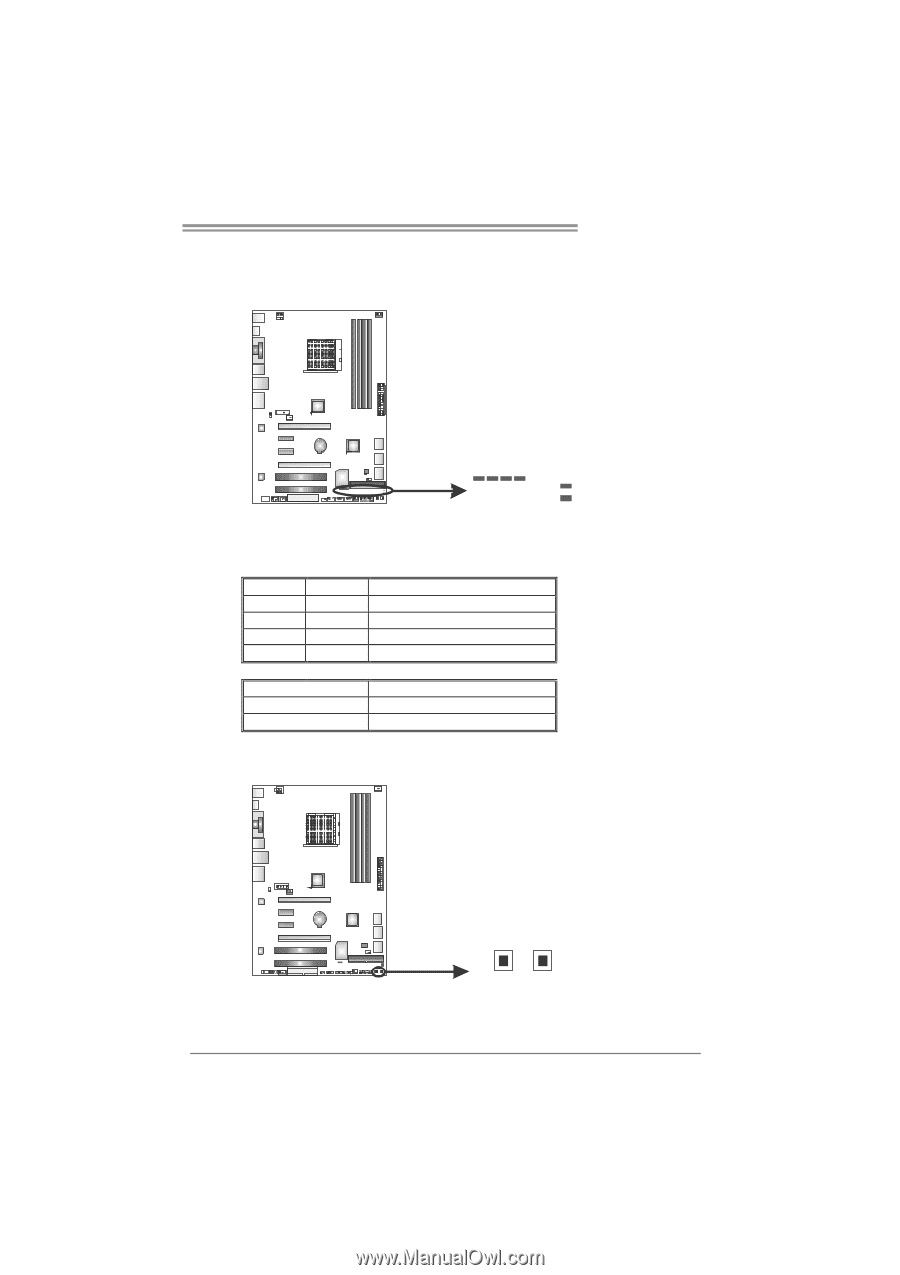
On-Board Buttons
There are 2 on-board buttons.
SW_RST
SW_PWR
SW_RST:
Reset
button.
SW_PWR:
Power Switch button.