Biostar TF560 A2 Setup Manual
Biostar TF560 A2 Manual
 |
View all Biostar TF560 A2 manuals
Add to My Manuals
Save this manual to your list of manuals |
Biostar TF560 A2 manual content summary:
- Biostar TF560 A2 | Setup Manual - Page 1
TF520 A2+/TF560 A2+ Setup Manual FCC Information and Copyright This equipment has been tested and found radiate radio frequency energy and, if not installed and used in accordance with the instructions, may cause harmful interference to radio communications. There is no guarantee that interference - Biostar TF560 A2 | Setup Manual - Page 2
How RAID Works 20 Chapter 5: OverClock Quick Guide 24 5.1 T-Power Introduction 24 5.2 T-Power BIOS Feature 25 5.3 T-Power Windows Feature 33 Chapter 6: Useful Help 38 6.1 Driver Installation Note 38 6.2 Award BIOS Beep Code 39 6.3 Extra Information 39 6.4 Troubleshooting 41 - Biostar TF560 A2 | Setup Manual - Page 3
A2+/TF560 A2+ 1.1 BEFORE YOU START Thank you for choosing our product. Before you start installing the motherboard, please make sure you follow the instructions below: „ Prepare a dry and stable working I/O Panel for ATX Case X 1 User's Manual X 1 Fully Setup Driver CD X 1 FDD Cable X 1 (optional) - Biostar TF560 A2 | Setup Manual - Page 4
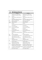
Motherboard Manual 1.3 MOTHERBOARD FEATURES TF520 A2+ TF560 A2+ Socket AM2 / AM2+ (By BIOS update) Socket AM2 / AM2+ (By BIOS update) AMD Athlon 64 / Athlon 64 x2 / Sempron AMD Athlon 64 / Athlon 64 x2 / Sempron processors processors CPU AMD 64 Architecture enables 32 and 64 bit AMD 64 - Biostar TF560 A2 | Setup Manual - Page 5
S/PDIF out connector x1 CPU Fan header x1 System Fan NVIDIA nTunes Features RAID 0 / 1 / 0+1 support Windows 2K / XP / VISTA OS Support Biostar Reserves the right to add or remove support for any OS With or without notice. TF520 A2+/TF560 A2+ TF560 A2+ ALC888 (Ver 5.x) / ALC662 (Ver - Biostar TF560 A2 | Setup Manual - Page 6
Motherboard Manual 1.4 REAR PANEL CONNECTORS (VER 5.X) PS/2 Mouse LAN PS/2 Keyboard COM1 USBX2 USBX2 USBX2 Center Rear Side Line In Line Out Mic In 1.5 REAR PANEL CONNECTORS (VER 6.X) PS/2 Mouse LA N PS/ 2 Keyboard COM1 USBX2 USBX2 USBX2 Line In/ Surround Line Out Mic I n 1/ Bass/ - Biostar TF560 A2 | Setup Manual - Page 7
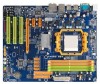
1.6 MOTHERBOARD LAYOUT JKBMS1 TF520 A2+/TF560 A2+ JCFAN1 JCOM1 JUSB2 JATXPWR2 JUSB1 DIMMA1 DIMMB1 DIMMA2 DIMMB2 J ATXPWR1 JUSBLAN1 IDE1 FDD1 AUDIO2 (for Ver 5.x) JAUDIO1 (for Ver 6.x) JATXPWR3 LAN PEX1_1 PEX1_2 nForce 520/560 PEX16_1 SATA1 SATA3 SATA2 BIOS SATA4 Codec PCI1 PCI2 - Biostar TF560 A2 | Setup Manual - Page 8
Motherboard Manual CHAPTER 2: HARDWARE INSTALLATION 2.1 INSTALLING CENTRAL PROCESSING UNIT (CPU) Step 1: Remove the socket protection cap. Step 2: Pull the lever toward direction A from the socket and then raise the lever up to a 90-degree angle. - Biostar TF560 A2 | Setup Manual - Page 9
TF520 A2+/TF560 A2+ Step 4: Hold the CPU down firmly, and then close the lever toward direct B to complete the installation. Step 5: Put the CPU Fan on the CPU and buckle it. Connect the CPU FAN power cable to the JCFAN1. This completes the installation. 7 - Biostar TF560 A2 | Setup Manual - Page 10
Motherboard Manual 2.2 FAN HEADERS These fan headers support cooling-fans built in the computer. The fan cable and connector may be different according to the fan manufacturer. Connect the fan cable to the connector while matching the black wire to pin#1. JCFAN1: CPU Fan Header 1 4 Pin Assignment - Biostar TF560 A2 | Setup Manual - Page 11
2.3 INSTALLING SYSTEM MEMORY A. Memory Modules TF520 A2+/TF560 A2+ DIMMA1 DIMMB1 DIMMA2 DIMMB2 1. Unlock a until the retaining chip snap back in place and the DIMM is properly seated. B. Memory Capacity DIMM Socket Location DIMMA1 DIMMB1 DIMMA2 DIMMB2 DDR2 Module 256MB/512MB/1GB/2GB 256MB/512MB - Biostar TF560 A2 | Setup Manual - Page 12
Motherboard Manual C. Dual Channel Memory installation To trigger the Dual Channel function of the motherboard, the memory module must meet the following requirements: Install memory module of the same density in pairs, shown in the following table. Duual Channel Status DIMMA1 DIMMB1 DIMMA2 DIMMB2 - Biostar TF560 A2 | Setup Manual - Page 13
TF520 A2+/TF560 A2+ 2.4 CONNECTORS AND SLOTS FDD1: Floppy Disk Connector The motherboard provides a standard floppy disk connector that supports 360K, 720K, 1.2M, 1.44M and 2.88M floppy disk types. This connector supports the provided floppy drive ribbon cables. 34 33 2 1 IDE1: Hard Disk - Biostar TF560 A2 | Setup Manual - Page 14
Motherboard Manual PEX16-1: PCI-Express x16 Slot - PCI-Express 1.0a compliant. - Maximum theoretical 0a compliant. - Data transfer bandwidth up to 250MB/s per direction; 500MB/s in total. - PCI-Express supports a raw bit-rate of 2.5Gb/s on the data pins. - 2X bandwidth over the traditional PCI - Biostar TF560 A2 | Setup Manual - Page 15
TF520 A2+/TF560 A2+ CHAPTER 3: HEADERS & JUMPERS SETUP 3.1 HOW TO SETUP JUMPERS The illustration shows how to set up jumpers. When the jumper cap is placed on pins, the - Biostar TF560 A2 | Setup Manual - Page 16
Motherboard Manual JATXPWR1: ATX Power Source Connector This connector allows user to connect 24-pin power connector on the ATX : ATX Power Source Connector By connecting this connector, it will provide +12V to CPU power circuit. 32 4 1 Pin Assignment 1 +12V 2 +12V 3 Ground 4 Ground 14 - Biostar TF560 A2 | Setup Manual - Page 17
TF520 A2+/TF560 A2+ JUSB3/JUSB4: Headers for USB 2.0 Ports at Front Panel This header allows user to connect additional USB cable on the PC front panel, and also - Biostar TF560 A2 | Setup Manual - Page 18
Motherboard Manual SATA1~SATA4: Serial ATA Connectors The motherboard has a PCI to SATA Controller with 4 channels SATA interface, it satisfies the SATA 2.0 spec to restore the BIOS safe setting and the CMOS data, please carefully follow the procedures to avoid damaging the motherboard. 13 Pin 1-2 - Biostar TF560 A2 | Setup Manual - Page 19
TF520 A2+/TF560 A2+ JSPDIF_OUT1: Digital Audio out Connector This connector allows user to connect the PCI bracket SPDIF output header. 13 Pin Assignment 1 +5V 2 SPDIF_OUT 3 Ground JPRNT1: Printer - Biostar TF560 A2 | Setup Manual - Page 20
Motherboard Manual JATXPWR3: Auxiliary Power for Graphics This connector is an auxiliary power Ground 3 Ground 4 VCC 4 On-Board LED Indicators There are 2 LED indicators on the motherboard to show system status. LED_D1 LED_D2 LED_D1 and LED_D2: These 2 LED indicate system power on diagnostics - Biostar TF560 A2 | Setup Manual - Page 21
On-Board Buttons There are 2 on-board buttons. TF520 A2+/TF560 A2+ RSTSW1 PWRSW1 PWRSW1: This is an on-board Power Switch button. RSTSW1: This is an on-board Reset button. 19 - Biostar TF560 A2 | Setup Manual - Page 22
Motherboard Manual CHAPTER 4: NVIDIA RAID FUNCTIONS 4.1 OPERATION SYSTEM z Supports Windows XP Home/Professional Edition, and Windows 2000 Professional. 4.2 RAID ARRAYS NVRAID supports and better utilization of disk capacity. 4.3 HOW RAID WORKS RAID 0: The controller "stripes" data across multiple - Biostar TF560 A2 | Setup Manual - Page 23
TF520 A2+/TF560 A2+ RAID 1: Every read and write is actually carried out in parallel across can be applied for high-availability solutions, or as a form of automatic backup that eliminates tedious manual backups to more expensive and less reliable media. Features and Benefits Drives: Minimum 2, and - Biostar TF560 A2 | Setup Manual - Page 24
Motherboard Manual RAID 0+1: RAID 0 drives can be mirrored using RAID 1 techniques. Resulting in a RAID 0+1 solution for improved performance plus resiliency. Features and Benefits Drives: Minimum 4, and maximum - Biostar TF560 A2 | Setup Manual - Page 25
A2+/TF560 A2 block data transfer rate same as a single disk. Write performance can be CPU intensive. Fault Tolerance: Yes. Disk 1 DATA 1 DATA 3 PARITY DATA , please refer to the Driver CD, or go to http://www.nvidia.com/page/pg_20011106217193.html to download NVIDIA nForce Tutorial Flash. 23 - Biostar TF560 A2 | Setup Manual - Page 26
Motherboard Manual CHAPTER 5: OVERCLOCK QUICK GUIDE 5.1 T-POWER INTRODUCTION Biostar T-Power is a whole new utility that is designed for overclock users. Based on many precise tests, Biostar Engineering Team (BET) has developed this ultimate overclock engine to raise system performance. No matter - Biostar TF560 A2 | Setup Manual - Page 27
TF520 A2+/TF560 A2+ 5.2 T-POWER BIOS FEATURE A. Overclocking Navigator Engine (O.N.E.): ONE provides two powerful overclocking engines: MOS and AOS for both Elite and Casual overclockers. Manual Overclock System (M.O.S.) MOS is designed for experienced overclock users. It allows users to customize - Biostar TF560 A2 | Setup Manual - Page 28
will increase CPU stability when overclocking. However, the CPU temperature will increase when CPU voltage is increased. NPT Fid Control: This function allows you to adjust the frequency ratio of CPU. Chipset Voltage: This function will increase chipset stability when overclocking. Memory Voltage - Biostar TF560 A2 | Setup Manual - Page 29
TF520 A2+/TF560 A2+ Automatic Overclock System (A.O.S.) For beginners in overclock field, BET had developed an easy, fast, and powerful feature to increase the system performance, named A.O.S. Based on many tests and experiments, A.O.S. provides 3 ideal overclock configurations that are able to - Biostar TF560 A2 | Setup Manual - Page 30
Motherboard Manual V12 Tech Engine: This setting will raise about 25%~30% of whole system performance. Notices: 1. Not all types of AMD CPU perform above overclock setting ideally; the difference will be based on the selected CPU model. B. CMOS Reloading Program (C.R.P.): It allows users to - Biostar TF560 A2 | Setup Manual - Page 31
TF520 A2+/TF560 A2+ C. Memory Integration Test (M.I.T.): This function is under "Overclocking Navigator Engine" item. MIT allows users to test memory compatibilities, and no extra devices or software are needed. Step 1: The default setting under this item is "Disabled"; the condition parameter - Biostar TF560 A2 | Setup Manual - Page 32
will automatically log in the default BIOS setting, and all overclock settings will be re-configured. E. Integrated Flash Program (I.F.P.): IFP is a safe and quick way to upgrade BIOS. Step 1: Go to Biostar website (http://www.biostar.com.tw) to download the latest BIOS file. Then, save the file - Biostar TF560 A2 | Setup Manual - Page 33
A2+/TF560 A2+ F. Smart Fan Function: Smart Fan Function is under "PC Health Status". This is a brilliant feature to control CPU Temperature vs. Fan speed. When enabling Smart Fan function, Fan speed is controlled automatically by CPU temperature. This function will protect CPU from overheat problem - Biostar TF560 A2 | Setup Manual - Page 34
Motherboard Manual CPU Fan Start The CPU fan starts to work when CPU temperature arrives to this set value. The range is from 0℃~127℃, with an interval of 1℃. CPU Fan Full speed When CPU temperature arrives to the set value, the CPU fan will work under Full Speed. The range is from 0℃~127℃, - Biostar TF560 A2 | Setup Manual - Page 35
5.3 T-POWER WINDOWS FEATURE TF520 A2+/TF560 A2+ 1. Desktop Icon After the T-Utility has been window you will see is Main Panel. Main Panel contains features as follows: a. Display the CPU Speed, CPU external clock, Memory clock, VGA clock, and PCI clock information. b. Contains About, Overclock - Biostar TF560 A2 | Setup Manual - Page 36
Motherboard Manual 3. Overclock/Overvoltage Panel Click the Overclock/Overvoltage button in the Main Panel, the button will be highlighted and the Overclock/Overvoltage Panel will show up as the following figure. As you can see, the Overclock Panel is on the upper side, and the Overvoltage Panel is - Biostar TF560 A2 | Setup Manual - Page 37
TF520 A2+/TF560 A2+ Overclock Panel contains these features: a. "Auto-Overclock": User can click this button and T-Utility will set the best and stable performance and frequency automatically. A warning dialog as below will show up to - Biostar TF560 A2 | Setup Manual - Page 38
Motherboard Manual e. "Save / Open Setting": Click Save button to save current setting to a file, and click Open button to load a previously saved setting. f. "Panel Color": Click this button to change the color of the panel. Overvoltage Panel contains these features: a. "CPU Voltage": This function - Biostar TF560 A2 | Setup Manual - Page 39
TF520 A2+/TF560 A2+ 5. About Panel Click the "about" button in Main Panel, the button will be highlighted and the About Panel will show up as the following figure. In this panel, you can get model name and detail information in hints of all the chipset that are related to overclocking. You can also - Biostar TF560 A2 | Setup Manual - Page 40
for better system performance. You will see the following window after you insert the CD The setup guide will auto detect your motherboard and operating system. Note: If this window didn't show up after you insert the Driver CD, please use file browser to locate and execute the file SETUP.EXE under - Biostar TF560 A2 | Setup Manual - Page 41
TF520 A2+/TF560 A2+ 6.2 AWARD BIOS BEEP CODE Beep Sound Meaning One long beep followed by two short Video card not found or video card beeps memory bad High-low siren sound CPU overheated System will shut down automatically One Short beep when system boot-up No error found during POST - Biostar TF560 A2 | Setup Manual - Page 42
Motherboard Manual B. CPU Overheated If the system shutdown automatically after power on system for seconds, that means the CPU protection function has been activated. When the CPU is over heated, the motherboard will shutdown automatically to avoid a damage of the CPU, and the system may not power - Biostar TF560 A2 | Setup Manual - Page 43
A2+/TF560 A2+ 6.4 TROUBLESHOOTING Probable Solution 1. No power to the system at all 1. Make sure power cable is Power light don't illuminate, fan securely plugged in. inside power supply does not turn 2. Replace cable. on. 3. Contact technical support Failure." Review system's equipment - Biostar TF560 A2 | Setup Manual - Page 44
Motherboard Manual APPENDENCIES: SPEC IN OTHER LANGUAGE GERMAN TF520 A2+ TF560 A2+ SockelAM2 / AM2+(Durch BIOS Aktualisierung) SockelAM2 / AM2+(Durch BIOS Aktualisierung) AMD Athlon 64 / Athlon 64 x2 / Sempron AMD Athlon 64 / Athlon 64 x2 / Sempron Prozessoren Prozessoren CPU Die AMD 64- - Biostar TF560 A2 | Setup Manual - Page 45
x1 CPU-Lüfter- NVIDIA nTunes onen Unterstützt RAID 0 / 1 / 0+1 Windows 2K / XP / VISTA Biostar behält sich das Recht vor, ohne OS-Unterstüt Ankündigung die Unterstützung für ein zung Betriebssystem hinzuzufügen oder zu entfernen. TF520 A2+/TF560 A2+ TF560 A2+ ALC888 (Ver 5.x) / ALC662 (Ver - Biostar TF560 A2 | Setup Manual - Page 46
Motherboard Manual FRANCE TF520 A2+ TF560 A2+ Socket AM2 / AM2+ (Par la mise à jour de BIOS) Socket AM2 / AM2+ (Par la mise à jour de BIOS) Processeurs AMD Athlon 64 / Athlon 64 x2 / Processeurs AMD Athlon 64 / Athlon 64 x2 / Sempron Sempron UC L'architecture AMD 64 permet le calcul 32 et - Biostar TF560 A2 | Setup Manual - Page 47
Fiche audio (Ver 6.x) x3 Dimensions 244 mm (l) X 305 mm (H) de la carte 244 mm (l) X 305 mm (H) Fonctionnali NVIDIA nTunes tés Prise en charge RAID 0 / 1 / 0+1 spéciales NVIDIA nTunes Prise en charge RAID 0 / 1 / 0+1 / 5 Windows 2K / XP / VISTA Windows 2K / XP / VISTA Support SE Biostar se - Biostar TF560 A2 | Setup Manual - Page 48
Motherboard Manual ITALIAN TF520 A2+ TF560 A2+ Socket AM2 / AM2+(Dall'aggiornamento di Socket AM2 / AM2+(Dall'aggiornamento di BIOS) BIOS) Processori AMD Athlon 64 / Athlon 64 x2 / Processori AMD Athlon 64 / Athlon 64 x2 / CPU Sempron Sempron L'architettura AMD 64 abilita la L' - Biostar TF560 A2 | Setup Manual - Page 49
x6 Connettore audio (Ver 6.x) x3 Dimension 244 mm (larghezza) x 305 mm (altezza) 244 mm (larghezza) x 305 mm (altezza) i scheda Caratterist nTunes NVIDIA iche Supporto RAID 0 / 1 / 0+1 speciali nTunes NVIDIA Supporto RAID 0 / 1 / 0+1 / 5 Windows 2K / XP / VISTA Sistemi Biostar si riserva il - Biostar TF560 A2 | Setup Manual - Page 50
Motherboard Manual SPANISH TF520 A2+ TF560 A2+ Conector AM2 / AM2+ (Por BIOS actualiza) Conector AM2 / AM2+ (Por BIOS actualiza) Procesadores AMD Athlon 64 / Athlon 64 x2 / Procesadores AMD Athlon 64 / Athlon 64 x2 / Sempron Sempron CPU La arquitectura AMD 64 permite el procesado de La - Biostar TF560 A2 | Setup Manual - Page 51
X6 Conector de sonido (Ver 5.x) X6 Conector de sonido (Ver 6.x) X3 244 mm. (A) X 305 Mm. (H) Funciones NVIDIA nTunes especiales Admite RAID 0 / 1 / 0+1 NVIDIA nTunes Admite RAID 0 / 1 / 0+1 / 5 Soporte de Windows 2K / XP / VISTA Windows 2K / XP / VISTA sistema Biostar se reserva el derecho - Biostar TF560 A2 | Setup Manual - Page 52
Motherboard Manual PORTUGUESE TF520 A2+ TF560 A2+ Socket AM2 / AM2+ (Por BIOS atualize) Socket AM2 / AM2+ (Por BIOS atualize) Processadores AMD Athlon 64 / Athlon 64 x2 / Processadores AMD Athlon 64 / Athlon 64 x2 / Sempron Sempron CPU A arquitectura AMD nVIDIA nForce 520 nVIDIA nForce 560 - Biostar TF560 A2 | Setup Manual - Page 53
CPU NVIDIA cas Suporta as funções RAID 0 / 1 / 0+1 especiais Windows 2K / XP / VISTA Sistemas A Biostar reserva-se o direito de adicionar ou operativos remover suporte para qualquer sistema suportados operativo com ou sem aviso prévio. TF520 A2+/TF560 A2+ TF560 A2+ ALC888 (Ver 5.x) / ALC662 (Ver - Biostar TF560 A2 | Setup Manual - Page 54
Motherboard Manual POLISH TF520 A2+ TF560 A2+ Socket AM2 / AM2+ (Przez BIOS modernizować) Socket AM2 / AM2+ (Przez BIOS modernizować) AMD Athlon 64 / Athlon 64 x2 / Sempron AMD Athlon 64 / Athlon 64 x2 / Sempron Procesor Procesory Procesory Architektura AMD 64 umożliwia przetwarzanie - Biostar TF560 A2 | Setup Manual - Page 55
Gniazdo audio (Ver 6.x) x3 Gniazdo audio (Ver 6.x) x3 Wymiary płyty 244 mm (S) X 305 mm (W) 244 mm (S) X 305 mm (W) Funkcje specjalne NVIDIA nTunes. Obsługa RAID 0 / 1 / 0+1 NVIDIA nTunes. Obsługa RAID 0 / 1 / 0+1 / 5 Obsluga Windows 2K / XP / VISTA systemu Biostar zastrzega sobie prawo - Biostar TF560 A2 | Setup Manual - Page 56
Hyper Transport и Cool'n'Quiet HyperTransport FSB 1GГц TF560 A2 AM2 / AM2 BIOS AMD Athlon 64 / Athlon 64 x2 / Sempron AMD 64 32 и 64 Hyper Transport и Cool'n'Quiet HyperTransport 1GГц Набор nVIDIA nForce 520 nVIDIA nForce 560 Super I/O Слоты DDR2 DIMM x 4 Слоты DDR2 DIMM - Biostar TF560 A2 | Setup Manual - Page 57
/2 x1 x1 Порт LAN x1 USB-порт x6 Ver 5.x) x6 Ver 6.x) x3 244 мм (Ш) X 305 мм (В) ые NVIDIA nTunes е RAID 0 / 1 / 0+1 тики NVIDIA nTunes RAID 0 / 1 / 0+1 / 5 Windows 2K / XP / VISTA Biostar OS OS с Windows 2K / XP / VISTA Biostar OS 55 - Biostar TF560 A2 | Setup Manual - Page 58
Motherboard Manual ARABIC TF560 A2+ TF520 A2+ ) / AM2 AM2 ) / AM2 AM2 AMD Athlon 64 Athlon 64 x2 / Sempron 32و 64ﺏﺖAMD 64 AMD Athlon 64 Athlon 64 x2 / Sempron 32و 64ﺏﺖAMD 64 Cool'n'Quietو Hyper Transport Cool'n'Quietو Hyper - Biostar TF560 A2 | Setup Manual - Page 59
6 USB 6 USB 6 Ver 5.x 6 Ver 5.x 3 Ver 6.x 3 Ver 6.x NVIDIA nTunes RAID 0 / 1 / 0+1 / 5 244 305 X Windows 2K / XP / VISTA Biostar NVIDIA nTunes RAID 0 / 1 / 0+1 244 305 X Windows 2K / XP / VISTA Biostar 57 - Biostar TF560 A2 | Setup Manual - Page 60
A2+ TF560 A2+ Socket AM2 / AM2+ (BIOS Socket AM2 / AM2+ (BIOS AMD Athlon 64 / Athlon 64 x2 / Sempron プロセ AMD Athlon 64 / Athlon 64 x2 / Sempron プロセ ッサ ッサ CPU AMD 64 32ビットと64 AMD 64 32ビットと64ビット計 1 GHz 1 GHz FSB nVIDIA nForce 520 nVIDIA nForce 560 - Biostar TF560 A2 | Setup Manual - Page 61
PS/2 x1 PS/2マウス x1 x1 LANポート x1 USBポート x6 Ver 5.x) x6 Ver 6.x) x3 244 mm (幅) X 305 mm (高さ) 特殊機能 NVIDIA nTunes RAID 0 / 1 / 0+1 NVIDIA nTunes RAID 0 / 1 / 0+1 / 5 Windows 2K / XP / VISTA Windows 2K / XP / VISTA OS Biostar OS Biostar OS 2007/05/21 59 - Biostar TF560 A2 | Setup Manual - Page 62
TF520 A2+/TF560 A2+ BIOS Manual BIOS Setup 1 1 Main Menu 3 2 Standard CMOS Features 7 3 Advanced BIOS Features 9 4 Advanced Chipset Features 16 5 Integrated Peripherals 18 6 Power Management Setup 25 7 PnP/PCI Configurations 29 8 PC Health Status 32 9 Over Clock Navigator 35 10 - Biostar TF560 A2 | Setup Manual - Page 63
TF520 A2+/TF560 A2+ BIOS Setup Introduction The purpose of this manual is to describe the settings in the Phoenix-Award™ BIOS Setup program on this motherboard. The Setup program allows users to modify the basic system configuration and save these settings to CMOS RAM. The power of CMOS RAM is - Biostar TF560 A2 | Setup Manual - Page 64
TF520 A2+/TF560 A2+ ACPI Support Phoenix-Award ACPI BIOS support Version 1.0b of Advanced Configuration and Power interface specification (ACPI). It provides ASL code for power management and device configuration capabilities as defined in the ACPI specification, developed by Microsoft, Intel and - Biostar TF560 A2 | Setup Manual - Page 65
TF520 A2+/TF560 A2+ 1 Main Menu Once you enter Phoenix-Award BIOS™ CMOS Setup Utility, the Main Menu will , the BIOS firmware is being continuously updated. The BIOS information described in this manual (Figure 1, 2, 3, 4, 5, 6, 7, 8, 9) is for your reference only. The actual BIOS information and - Biostar TF560 A2 | Setup Manual - Page 66
TF520 A2+/TF560 A2+ Advanced Chipset Features This submenu allows overclock expertise and beginner. CMOS Reload Program (C.R.P.) The CMOS Reload Program (CRP) allows you to save different CMOS settings into BIOS-ROM. Load Optimized Defaults This selection allows you to reload the BIOS when problem - Biostar TF560 A2 | Setup Manual - Page 67
TF520 A2+/TF560 A2+ Set Supervisor Password Setting the supervisor password will prohibit not be able to change them. Save & Exit Setup Save all configuration changes to CMOS (memory) and exit setup. Confirmation message will be displayed before proceeding. Exit Without Saving Abandon all changes - Biostar TF560 A2 | Setup Manual - Page 68
TF520 A2+/TF560 A2+ Integrate Flashing Program This is a very safe way to upgrade BIOS. By pressing "Enter" key for three times, and the upgrading process will be completed easily. 6 - Biostar TF560 A2 | Setup Manual - Page 69
TF520 A2+/TF560 A2+ 2 Standard CMOS Features The items in Standard CMOS Setup Menu are divided into several categories. Each category includes no, one or more than one setup - Biostar TF560 A2 | Setup Manual - Page 70
TF520 A2+/TF560 A2+ Item Drive A Halt On Base Memory Extended Memory Total Memory Options 360K, 5.25 in 1.2M, 5.25 in 720K, 3.5 want the BIOS to stop the POST process and notify you. Displays the amount of conventional memory detected during boot up. Displays the amount of extended memory detected - Biostar TF560 A2 | Setup Manual - Page 71
TF520 A2+/TF560 A2+ 3 Advanced BIOS Features „ Figure 3: Advanced BIOS Setup Cache Setup 9 - Biostar TF560 A2 | Setup Manual - Page 72
TF520 A2+/TF560 A2+ CPU Internal Cache Depending on the CPU/chipset in use, you may be able to increase memory access time with this option. Enabled (default) Enable cache. Disab led Disable cache. External Cache This option enables or disables "Level 2" secondary cache on the CPU, which may - Biostar TF560 A2 | Setup Manual - Page 73
TF520 A2+/TF560 A2+ Removable Device Priority Select Removable Boot Device Priority. The Choices: Floppy Disks, Zip100, USB-FDD0, USB-FDD1, USB-ZIP0, USB-ZIP1, LS120. Hard Disk Boot Priority The BIOS will attempt to arrange the Hard Disk boot sequence automatically. You can change the Hard Disk - Biostar TF560 A2 | Setup Manual - Page 74
TF520 A2+/TF560 A2+ CD-ROM Boot Priority The Choices: Pri. Master, Pri. Slave, Sec. Master, Sec. Slave, USB-CDROM0, USB-CDROM1. First/Second/Third Boot Device The BIOS will attempt to load the operating system in this order. The Choices: Removable, Hard Disk, CDROM, Legacy LAN, Disabled. Boot Other - Biostar TF560 A2 | Setup Manual - Page 75
TF520 A2+/TF560 A2+ CPU Feature AMD K8 Cool&Quiet control The item allows you select K8 Cool'n' sector. If this function is enabled and an attempt is made to write to the boot sector, BIOS will display a warning message on the screen and sound an alarm beep. Disabled (default) Virus protection - Biostar TF560 A2 | Setup Manual - Page 76
TF520 A2+/TF560 A2+ Boot Up NumLock Status Selects the NumLock State after the system switched on. The Choices: On (default) Numpad is number keys. Off Numpad is arrow - Biostar TF560 A2 | Setup Manual - Page 77
TF520 A2+/TF560 A2+ APIC MODE Selecting Enabled enables APIC device mode reporting from the BIOS to the operating system. The Choices: Enabled (default), Disabled. MPS Version Control For OS The BIOS supports version 1.1 and 1.4 of the Intel multiprocessor specification. Select version supported by - Biostar TF560 A2 | Setup Manual - Page 78
A2+/TF560 A2+ 4 Advanced Chipset Features This submenu allows you to configure the specific features of the chipset installed on your system. This chipset manage bus speeds and access to system memory : Disabled (default), Enabled. SSE/SSE2 instructions This item allows you to enable/disable SSE/SSE2 - Biostar TF560 A2 | Setup Manual - Page 79
TF520 A2+/TF560 A2+ System BIOS Cacheable Selecting the "Enabled" option allows caching of the system BIOS ROM at F0000h-FFFFFh, which is able to improve the system performance. However, any programs that attempts to write to this memory block will cause conflicts and result in system errors. The - Biostar TF560 A2 | Setup Manual - Page 80
TF520 A2+/TF560 A2+ 5 Integrated Peripherals „ Figure 5. Integrated Peripherals IDE Function Setup Highlight the "Press Enter" label next to the "IDE Function Setup" label and press enter key will take you a submenu with the following options: 18 - Biostar TF560 A2 | Setup Manual - Page 81
TF520 A2+/TF560 A2+ MCP Storage Config SATA Operation Mode This option allows you to choose SATA RAID. The Choices: Disabled (default), Enabled. OnChip IDE Channel 0 The motherboard chipset contains a PCI IDE interface with support for two IDE channels. Select "Enabled" to activate the first and/or - Biostar TF560 A2 | Setup Manual - Page 82
TF520 A2+/TF560 A2+ Primary Master/Slave UDMA Ultra DMA function can be implemented if it is supported by the IDE hard drives in your system. As well, your operating environment requires a DMA driver (Windows 95 or OSR2 may need a third party IDE bus master driver). If your hard drive and your - Biostar TF560 A2 | Setup Manual - Page 83
TF520 A2+/TF560 A2+ Onboard Device Highlight the "Press Enter" label next to the "Onboard V2.0 (default), Disabled, V1.1 USB Memory Type This option allows you to choose the USB memory type. The Choices: SHADOW (default), Base Memory(640K). USB Keyboard Support This item allows you to enable or - Biostar TF560 A2 | Setup Manual - Page 84
TF520 A2+/TF560 A2+ USB Mouse Support This item allows you to enable or disable the USB Mouse Legacy Support. Enabled USB Mouse Support. Disabled (default) Disable USB Mouse Support. USB Storage Support This item allows you to enable or disable the USB storage device Legacy Support. Enabled ( - Biostar TF560 A2 | Setup Manual - Page 85
TF520 A2+/TF560 A2+ SuperIO Device Press Enter to configure the Super I/O device. Onboard FDC Controller Select enabled if your system has a floppy disk controller (FDC) installed on the - Biostar TF560 A2 | Setup Manual - Page 86
TF520 A2+/TF560 A2+ Parallel Port Mode This item allows you to determine how the parallel port should function. The default value is SPP. The Choices: SPP (default) Using - Biostar TF560 A2 | Setup Manual - Page 87
TF520 A2+/TF560 A2+ 6 Power Management Setup The Power Management Setup Menu allows you to configure your system to utilize energy conservation and power up/ suspend type under the ACPI operating system. The Choices: S1 (POS) (default) Power on Suspend S3 (STR) Suspend to RAM S1 & S3 POS+STR 25 - Biostar TF560 A2 | Setup Manual - Page 88
TF520 A2+/TF560 A2+ Down = 15 min Max. Power Saving Maximum power management only available for sl CPU's. Suspend Mode = 1 min. HDD Power Down = 1 min. User Define This option only writes blanks to the video buffer. DPMS Support (default) Initial display power management signaling. HDD Power Down - Biostar TF560 A2 | Setup Manual - Page 89
A2+/TF560 A2 -Off This item allows you to enable or disable Wake On LAN from Soft-Off function. The Choices: Disabled (default), Enabled. spec ify. Note: If you have change the setting, you must let the system boot up until it goes to the operating system, before this function will work. HPET Support - Biostar TF560 A2 | Setup Manual - Page 90
TF520 A2+/TF560 A2+ POWER ON Function This item allows you to choose the power on method. The Choices: Button Only(default), Password, Hot Key, Mouse Move/Click, Mouse - Biostar TF560 A2 | Setup Manual - Page 91
TF520 A2+/TF560 A2+ 7 PnP/PCI Configurations This section describes configuring the PCI bus system. PCI, or Personal Computer Interconnect, is a system which allows I/O devices to operate at speeds nearing the speed of the CPU itself uses when communicating with its own special components. This - Biostar TF560 A2 | Setup Manual - Page 92
A2+/TF560 A2+ Reset Configuration Data The system BIOS supports update ESCD to the memory locations. These locations are reserved in the system BIOS. If the Disabled (default) option is chosen, the system's ESCD will update Resources Controlled By" is set to " Manual". IRQ-5 assigned to PCI Device IRQ - Biostar TF560 A2 | Setup Manual - Page 93
TF520 A2+/TF560 A2+ PCI / VGA Palette Snoop Some old graphic controllers need to "snoop" on the VGA palette and then map it to their display as a way to - Biostar TF560 A2 | Setup Manual - Page 94
TF520 A2+/TF560 A2+ 8 PC Health Status „ Figure 8: PC Health Status Fan Control Setup 32 - Biostar TF560 A2 | Setup Manual - Page 95
TF520 A2+/TF560 A2+ SYS FAN1 Control By The Choice "smart" can make your northbridge FAN to reduce noise. The Choices: Always ON (default), Smart. CPU FAN Control By The Choice "smart" can make your CPU FAN to reduce noise. The Choices: Always ON (default), Smart. CPU Fan Off If the CPU - Biostar TF560 A2 | Setup Manual - Page 96
TF520 A2+/TF560 A2+ CPU Vcore, Chipset Voltage, +3.3V, +5.0V, +12.0V, DDR Voltage, HT Voltage, 5V, Voltage Battery Detect the system's voltage status automatically. CPU Temperature This field displays the current temperature of CPU. CPU FAN Speed This field displays the current speed of CPU fan. - Biostar TF560 A2 | Setup Manual - Page 97
TF520 A2+/TF560 A2+ 9 Over Clock Navigator OverClock Navigator OverClock .Navigator is designed for beginners in overclock field. Based on many test and experiments from Biostar Engineer Team, OverClock Navigator provides 3 default overclock configurations that are able to raise the system - Biostar TF560 A2 | Setup Manual - Page 98
TF520 A2+/TF560 A2+ Auto OverClock System The Overclock Navigator provides 3 different engines helping you to overclock your system. These every AMD CPU performs the above overclock setting ideally; the difference may vary with the installed CPU model. 2. From BET experiment, the Atholon64 FX CPU is - Biostar TF560 A2 | Setup Manual - Page 99
TF520 A2+/TF560 A2+ Manual Overclock System (M.O.S.) MOS is designed for experienced overclock users. It allows users to customize personal overclock setting. Note: Based on our test results; the overclock function achieved the best performance on AMD 3000+ CPU DRAM Configuration 37 - Biostar TF560 A2 | Setup Manual - Page 100
TF520 A2+/TF560 A2+ Timing Mode This item allows you to choose to manually or automatically regulate the DDR T imin g. The Choices: Auto (default), MaxMemClk. Memory Clock Value OR Limi The Choices: DDR 400 (default), DDR 533, DDR 667, DDR 800. DQS Training Control The Choices: Perform DQS, Skip DQS - Biostar TF560 A2 | Setup Manual - Page 101
TF520 A2+/TF560 A2+ Trfc2 for DIMM2 The Choices: 75ns (default) , 105ns, 127.5ns, Minimum RAS Active T The Choices: 18 bus clocks (default), 5-17 bus clocks. CPU Frequency This item allows you to select the CPU Frequency. The Choices: 200 (default), 200~450. K8NB HT Speed The Choices: AUTO - Biostar TF560 A2 | Setup Manual - Page 102
TF520 A2+/TF560 A2+ PCIE Spread Spectrum This item allows you to select the PCIE ~ x25: 5000Mhz (differs from CPU) Chipset Voltage This function allows you to adjust the chipset voltage. The Choices: AUTO (default), 1.250V, 1.275V, 1.300V, 1.325V Memory Voltage This function allows you to adjust - Biostar TF560 A2 | Setup Manual - Page 103
TF520 A2+/TF560 A2+ Integrated Memory Test Integrated Memory Test allows users to test memory module compatibilities without additional device or software. Step 1: This item is disabled on default; change it to "Enable" to precede memory test. Step 2: When the process is done, change the setting - Biostar TF560 A2 | Setup Manual - Page 104
TF520 A2+/TF560 A2+ 10 CMOS Reload Program (C.R.P.) The CMOS Reload Program (CRP) allows you to save different CMOS settings into BIOS-ROM. You may reload any saved CMOS setting to change system configurations. Moreover, you may save your ideal overclock setting for easier overclocking. There are 50
-
 1
1 -
 2
2 -
 3
3 -
 4
4 -
 5
5 -
 6
6 -
 7
7 -
8
-
9
-
10
-
11
-
12
-
13
-
14
-
15
-
16
-
17
-
18
-
19
-
20
-
21
-
22
-
23
-
24
-
25
-
26
-
27
-
28
-
29
-
30
-
31
-
32
-
33
-
34
-
35
-
36
-
37
-
38
-
39
-
40
-
41
-
42
-
43
-
44
-
45
-
46
-
47
-
48
-
49
-
50
-
51
-
52
-
53
-
54
-
55
-
56
-
57
-
58
-
59
-
60
-
61
-
62
-
63
-
64
-
65
-
66
-
67
-
68
-
69
-
70
-
71
-
72
-
73
-
74
-
75
-
76
-
77
-
78
-
79
-
80
-
81
-
82
-
83
-
84
-
85
-
86
-
87
-
88
-
89
-
90
-
91
-
92
-
93
-
94
-
95
-
96
-
97
-
98
-
99
-
100
-
101
-
102
-
103
-
104
 |
 |

TF520 A2+/TF560 A2+ Setup Manual
FCC Information and Copyright
This equipment has been tested and found to comply with the limits of a Class
B digital device, pursuant to Part 15 of the FCC Rules. These limits are designed
to provide reasonable protection against harmful interference in a residential
installation. This equipment generates, uses, and can radiate radio frequency
energy and, if not installed and used in accordance with the instructions, may
cause harmful interference to radio communications. There is no guarantee
that interference will not occur in a particular installation.
The vendor makes no representations or warranties with respect to the
contents here and specially disclaims any implied warranties of merchantability
or fitness for any purpose. Further the vendor reserves the right to revise this
publication and to make changes to the contents here without obligation to
notify any party beforehand.
Duplication of this publication, in part or in whole, is not allowed without first
obtaining the vendor’s approval in writing.
The content of this user’s manual is subject to be changed without notice and
we will not be responsible for any mistakes found in this user’s manual. All the
brand and product names are trademarks of their respective companies.