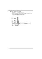
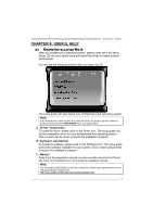
Biostar VIOTECH 3200 Setup Manual - Page 15
F_AUDIO1: Front Panel Audio Header, JCMOS1: Clear CMOS Header, Clear CMOS Procedures - + bios
 |
View all Biostar VIOTECH 3200 manuals
Add to My Manuals
Save this manual to your list of manuals |
Page 15 highlights
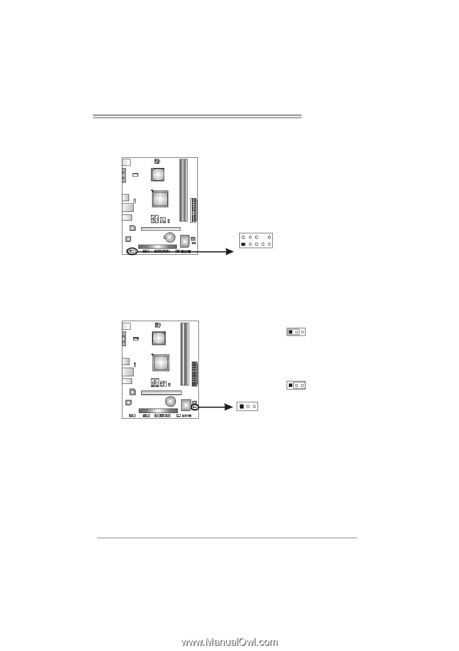
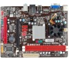
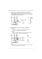
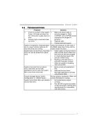
Viotech 3200+ F_AUDIO1: Front Panel Audio Header This header allows user to connect the front audio output cable with the PC front panel. 2 10 Pin Assignment 1 Mic Left in 2 Ground 3 Mic Right in 4 GPIO 5 Right line in 6 Jack Sense 7 Front Sense 8 Key 9 Left line in 10 Jack Sense 1 9 JCMOS1: Clear CMOS Header Placing the jumper on pin2-3 allows user to restore the BIOS safe setting and the CMOS data. Please carefully follow the procedures to avoid damaging the motherboard. 13 Pin 1-2 Close: Normal Operation (Default). 13 13 Pin 2-3 Close: Clear CMOS data. ※ Clear CMOS Procedures: 1. Remove AC power line. 2. Set the jumper to "Pin 2-3 close". 3. Wait for five seconds. 4. Set the jumper to "Pin 1-2 close". 5. Power on the AC. 6. Load Optimal Defaults and save settings in CMOS. 13
-
 1
1 -
2
-
3
-
4
-
5
-
6
-
7
-
8
-
9
-
 10
10 -
 11
11 -
 12
12 -
 13
13 -
 14
14 -
 15
15 -
 16
16 -
 17
17 -
 18
18 -
 19
19 -
 20
20 -
21
-
22
-
23
-
24
-
25
-
26
-
27
-
28
-
29
-
30
-
31
-
32
-
33
-
34
-
35
-
36
-
37
 |
 |