Biostar VIOTECH 3200 Setup Manual - Page 5
Rear Panel Connectors - board +
 |
View all Biostar VIOTECH 3200 manuals
Add to My Manuals
Save this manual to your list of manuals |
Page 5 highlights
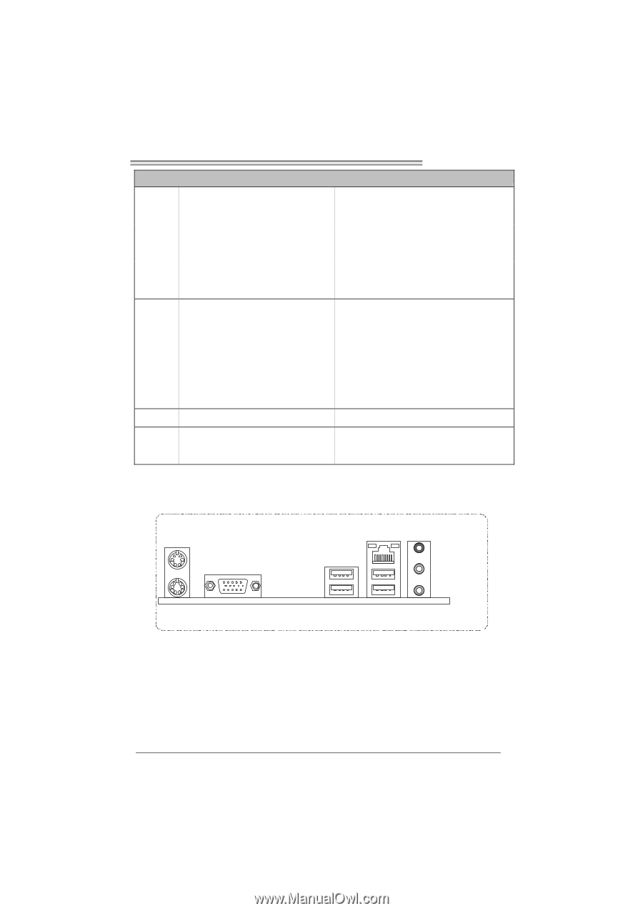
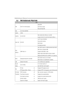
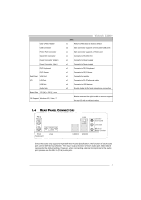
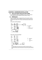
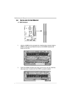
Clear CMOS Header USB Connector Printer Port Connector Serial Port Connector Power Connector (24pin) Power Connector (4pin) PS/2 Keyboard PS/2 Mouse Real Panel VGA Port I/O LAN Port USB Port Audio Jack Board Size 170 (W) x 220 (L) mm OS Support Windows XP / Vista / 7 Viotech 3200+ SPEC x1 Restore CMOS data to factory default x2 Each connector supports 2 front panel USB ports x1 Each connector supports 1 Printer port x1 Connects to RS-232 Port x1 Connects to Power supply x1 Connects to Power supply x1 Connects to PS/2 Keyboard x1 Connects to PS/2 Mouse x1 Connects to monitor x1 Connects to RJ-45 ethernet cable x4 Connects to USB devices x3 Provide Audio-In/Out and microphone connection Biostar reserves the right to add or remove support for any OS with or without notice. 1.4 REAR PANEL CONNECTORS PS/2 Mouse LAN PS/2 Keyboard VGA USBX2 USBX2 Line In/ Surround Line Out Mic In 1/ Bass/ Center Since the audio chip supports High Definition Audio Specification, the function of each audio jack can be defined by software. The input / output function of each audio jack listed above represents the default setting. However, when connecting external microphone to the audio port, please use the Mic In (Pink) audio jack. 3
-
 1
1 -
 2
2 -
 3
3 -
 4
4 -
 5
5 -
 6
6 -
 7
7 -
 8
8 -
 9
9 -
 10
10 -
 11
11 -
12
-
13
-
14
-
15
-
16
-
17
-
18
-
19
-
20
-
21
-
22
-
23
-
24
-
25
-
26
-
27
-
28
-
29
-
30
-
31
-
32
-
33
-
34
-
35
-
36
-
37
 |
 |