Biostar VIOTECH 3200 Setup Manual - Page 7
Hardware Installation - cpu via +
 |
View all Biostar VIOTECH 3200 manuals
Add to My Manuals
Save this manual to your list of manuals |
Page 7 highlights
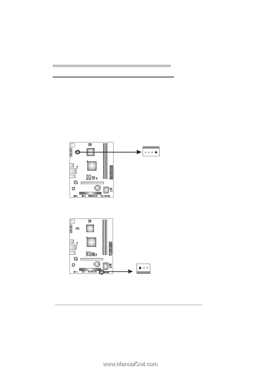
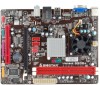
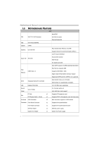
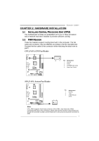
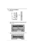
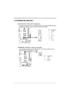
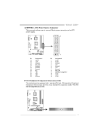
Viotech 3200+ CHAPTER 2: HARDWARE INSTALLATION 2.1 INSTALLING CENTRAL PROCESSING UNIT (CPU) The motherboard includes an embedded VIA C7-D or Nano processor, and a heatsink has been installed to provide sufficient cooling. 2.2 FAN HEADERS These fan headers support cooling-fans built in the computer. The fan cable and connector may be different according to the fan manufacturer. Connect the fan cable to the connector while matching the black wire to pin#1. CPU_FAN1: CPU Fan Header 4 1 Pin Assignment 1 Ground 2 Power 3 FAN RPM rate sense 4 Smart Fan Control SYS_FAN1: System Fan Header 13 Pin Assignment 1 Ground 2 +12V 3 FAN RPM rate sense Note: CPU_FAN1 supports 4-pin head connector; SYS_FAN1, 3-pin head one. When connecting with wires onto connectors, please note that the red wire is the positive and should be connected to pin#2, and the black wire is Ground and should be connected to GND. 5
-
 1
1 -
 2
2 -
 3
3 -
 4
4 -
 5
5 -
 6
6 -
 7
7 -
 8
8 -
 9
9 -
 10
10 -
 11
11 -
 12
12 -
13
-
14
-
15
-
16
-
17
-
18
-
19
-
20
-
21
-
22
-
23
-
24
-
25
-
26
-
27
-
28
-
29
-
30
-
31
-
32
-
33
-
34
-
35
-
36
-
37
 |
 |