Black & Decker GSP401 Instruction Manual - Page 7
Functional Description
 |
View all Black & Decker GSP401 manuals
Add to My Manuals
Save this manual to your list of manuals |
Page 7 highlights
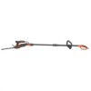
FUNCTIONAL DESCRIPTION 1. Lock-off button 2. Trigger switch 3. Power cord 4. Blade release button 5. Blade cover 6. Guard 7. Pole 8. Pole trigger switch 9. Pole lock-off button 10. Pole power cord 11. Tool basket 12. Angle adjustment lever 13. Pole extension coupling 14. Cord retainer 15. Grass Shear blade 16. Shrubber blade 17. Auxillary handle 18. Handle lock 19. Handle bolt 20. Auxillary handle knob 21. Pole plug 22. Adapter 1 2 22 9 10 7 6 5 3 4 15 8 14 12 11 13 21 17 16 19 18 20 preparing your tool for use WARNING: Read and understand all A instructions. Failure to follow all instructions 23 18 listed below may result in electric shock, fire and/or serious personal injury. Assembly WARNING: To prevent accidental operation, ensure that the tool is unplugged before performing the following operations. Failure to do this could result in serious personal injury. Fitting the auxiliary handle • Twist the auxiliary handle knob (20) to remove it and slide the handle lock (18) out of the auxiliary handle. • Push the auxiliary handle (17) onto the lower tube (23) of the pole. • Slide the handle lock (18) into position on the auxiliary handle ensuring the semicircular side faces the tube and the key feature on the auxiliary handle is in the groove on the tube as shown in figure A. • Insert the handle bolt (19) through hex shaped bolt hole (24) in the auxiliary handle. Push the bolt through the handle assembly and thread the auxillary handle knob (20) onto the bolt as shown in figure B. Note: The auxiliary handle can be adjusted along the tube. Simply loosen the auxillary handle knob and position the handle as desired. Retighten the knob to secure the auxiliary handle. 17 B 20 19 24 Fitting and removing the blade WARNING: To prevent accidental operation, ensure that the tool is unplugged before performing the following operations. Failure to do this could result in serious personal injury. The grass shear blade (15) has been designed for trimming grass and weeds. The shrubber blade (16) has been designed for trimming bushes and shrubs. 7
-
 1
1 -
 2
2 -
 3
3 -
 4
4 -
 5
5 -
 6
6 -
 7
7 -
 8
8 -
 9
9 -
 10
10 -
 11
11 -
 12
12 -
13
-
14
-
15
-
16
-
17
-
18
-
19
-
20
-
21
-
22
-
23
-
24
-
25
-
26
-
27
-
28
-
29
-
30
-
31
-
32
-
33
-
34
-
35
-
36
-
37
-
38
-
39
-
40
-
41
-
42
-
43
-
44
-
45
-
46
 |
 |
