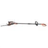
Black & Decker GSP401 Instruction Manual - Page 8
To Remove The Blade Cover, To Remove And Install Blades, To Install The Blade Cover
 |
View all Black & Decker GSP401 manuals
Add to My Manuals
Save this manual to your list of manuals |
Page 8 highlights
To remove the blade cover • Press and pull back on the blade release button (4) as shown in figure C. • Slide the blade cover (6) back and lift it off. To Remove and install bladeS • Press and pull back on the blade release button (4) as shown in figure C. • Slide the blade cover (6) back and lift it off. • With blade cover removed, lift blade out of tool. • Place desired blade flat side facing out, onto the four retaining pins located at each corner and one center pin. • Hold the blade onto the pins, locate the blade cover (6) as shown in figure D. To install the blade cover • While holding the blade onto the pins (Fig. D). Place blade cover front clips under the lip of the blade housing and press the blade cover downward to secure the blade as shown in figure E. Note: No alignment of blade with drive pin is required and operation of the blade cover release button is not required when re-fitting the blade cover. Assembly of pole unit WARNING: To prevent accidental operation, ensure that the tool is unplugged before performing the following operations. Failure to do this could result in serious personal injury. mounting the tool WARNING: Blades coast after turn off. • Unlock the tool basket (11) by lifting up on the latch lever (25). Swing open the tool basket door (26) as shown in figure F. • Slide the tool fully into the tool basket as shown in figure G. The arrow on the tool body and arrow on the tool basket must be aligned. • Close the tool basket door and secure the latch, ensuring the latch lever retaining loop (27) is fully seated under the hooks (28) on the tool basket door as shown in figure H. Note: The arrow on the tool body and the arrow on the tool basket must point towards each other as shown in figure H. F 25 26 C 4 27 28 6 G D H E 27 28 8


