Bosch HBL8651UC Installation Instructions - Page 9
Combination Oven Pre-Assembly
 |
View all Bosch HBL8651UC manuals
Add to My Manuals
Save this manual to your list of manuals |
Page 9 highlights
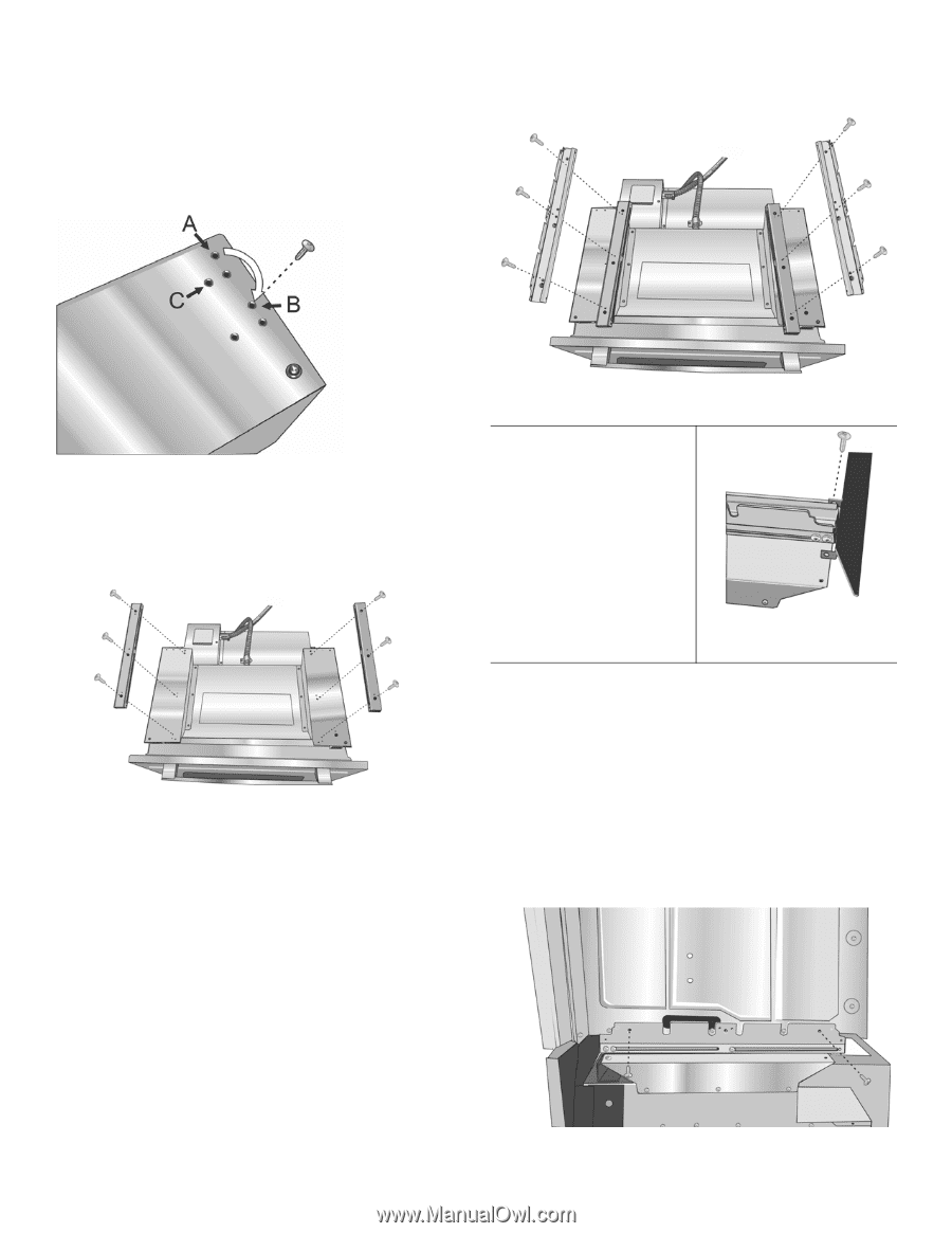
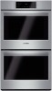
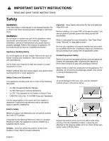
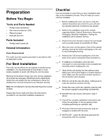
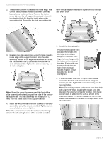
Combination Oven Pre-Assembly 2. The screw in position A (nearest the inside edge, near control panel) must be moved to allow the universal bracket to be postioned there. Remove the inside screw (A) from the left support bracket and reinsert it into the third hole (B) from the inside edge of the support bracket. Repeat for the right support bracket. taller vertical edge of the bracket is positioned to the outside of the oven. 3. Reattach the slide assemblies using the holes near the inside edge of the support bracket. Align the slide assembly parallel to the edge of the bracket and insert the first screw in hole (C). Insert all three screws for each slide assembly. Tighten the screws securely, but do not overtighten. Note: When the correct holes are used, the front of the slide assembly will extend just past the edge of the horizontal support bar. The slide assembly will be about 1/8" (3 mm) from the inside edge of the support bracket. 4. Install the two universal connector brackets to the slide assemblies using the screws provided. Tighten screws securely, but do not overtighten. Note: The universal connector brackets are interchangeable for the left and right sides of the oven. Be sure the 5. Install the decorative trim. Position the decorative trim piece so the flanges with the holes in them face away from the oven door. Align the inner flanges with the inside of the universal brackets. Fasten with one screw each into the end hole of the universal bracket. Tighten screws securely, but do not overtighten. 6. Place the steam oven unit on top of the universal connector brackets and fasten in place using two screws per side. Tighten the screws securely, but do not overtighten. Note: The existing screws in the steam oven base help with alignment. When lowering the steam oven into place on the universal connector bracket, allow these screw heads to slide into the slots as shown in the illustration below. The screw nearest the front of the steam oven slides into the base of the slope at the front of the bracket. English 6
-
 1
1 -
2
-
3
-
 4
4 -
 5
5 -
 6
6 -
 7
7 -
 8
8 -
 9
9 -
 10
10 -
 11
11 -
 12
12 -
 13
13 -
 14
14 -
15
-
16
-
17
-
18
-
19
-
20
-
21
-
22
-
23
-
24
-
25
-
26
-
27
-
28
-
29
-
30
-
31
-
32
-
33
-
34
-
35
-
36
-
37
-
38
-
39
-
40
-
41
-
42
-
43
-
44
-
45
-
46
-
47
-
48
-
49
-
50
-
51
-
52
-
53
-
54
-
55
-
56
 |
 |