Bosch WTMC8320US Installation and Use & Care (all languages) - Page 8
Accessories, Installation - tools
 |
UPC - 825225855583
View all Bosch WTMC8320US manuals
Add to My Manuals
Save this manual to your list of manuals |
Page 8 highlights
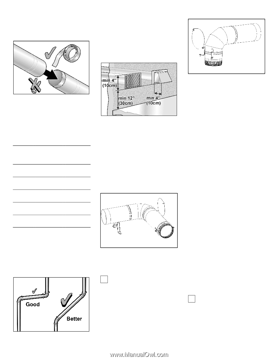
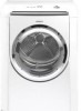
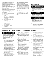
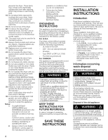
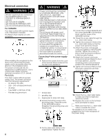
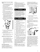
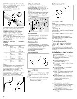
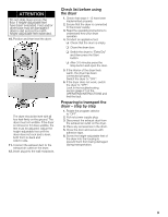
DO NOT assemble the ductwork with screws or fasteners that extend into the duct. They will serve as an accumulation point for lint. Joints should be secured with aluminum tape. Exhaust vent hood The exhaust duct must end with an approved exhaust vent hood with swing out damper(s). DO NOT use an exhaust vent hood with magnetic latches. To avoid exhaust restriction, the outlet must be a minimum of 12 inches (30 cm) above ground level or any other obstructing surface. Bottom exhaust kit All joints should be tight to avoid leaks. The male end of each duct section must point away from the dryer. Whether connecting to an existing venting system or a new venting system, make sure that all ducting is clean and free of lint. The maximum permitted length for both rigid and flexible metal duct is shown in the table below. Number of Rigid Duct 90° Turns or Elbows Flexible Duct 0 66 ft. 45 ft. (2011 cm) (1372 cm) 1 56 ft. 36 ft. (1707 cm) (1097 cm) 2 48 ft. 29 ft. (1463 cm) (884 cm) 3 39 ft. 22 ft. (1189 cm) (671 cm) 4 30 ft. (914 cm) 16 ft. (488 cm) Note: Side and bottom exhaust installations have a 90° turn inside the dryer. To determine maximum exhaust length, add one 90° turn to the chart. More than two 90° turns are not recommended. For best performance, separate all turns by at least 4 ft. of straight duct, including distance between last turn and exhaust hood. Required parts The parts required for the exhaust air system (elbows, lines, exhaust air outlets) are not included in standard delivery of the dryer. Accessories The parts required for the exhaust air system can be obtained from customer service or your local dealer. Please follow the installation instructions supplied by the appropriate manufacturer! Side exhaust kit part no. WTZ 1265 Note: The maximum permitted number of 90° elbows (including this side exhaust kit) is four! i Special tool for cutting the hole in prepared side panel is required. Contact local dealer! part no. WTZ 1270 Note: The maximum permitted number of 90° elbows (including this side exhaust kit) is four! Left hinge kit part no. WTZ 1260 for all dryers except duo tone silver part no. WTZ 126S for duo tone silver dryers The door catch can be reversed if necessary. The door is hinged on the right at the factory. Pedestal Mounting Kit Part no. WTZ 1295 (for white dryer). Part no. WTZ 1295P (for duo tone dryer) If mounting the dryer on the pedestal follow the instructions supplied with the pedestal. Installation ć step by step 1. Unpack the dryer. 2. Remove all objects from the drum. 3. Check the dryer for visible damage. 4. Position the dryer near the installation location. 5. If required, change the door hinges to the left (see page 5). 6. If required install the exhaust air outlet on the dryer (see page 7). 7. Have the power supply cord fitted by an authorized technician (see page 8). 8. Install exhaust duct, if necessary. Follow the installation instructions supplied by the appropriate manufacturer! i If space is very restricted, it is recommended to fit the initial parts of the exhaust duct to the dryer before the dryer is moved to its final installation location. 9. Move the dryer to its final location and align. 8
-
 1
1 -
2
-
 3
3 -
 4
4 -
 5
5 -
 6
6 -
 7
7 -
 8
8 -
 9
9 -
 10
10 -
 11
11 -
 12
12 -
 13
13 -
14
-
15
-
16
-
17
-
18
-
19
-
20
-
21
-
22
-
23
-
24
-
25
-
26
-
27
-
28
-
29
-
30
-
31
-
32
-
33
-
34
-
35
-
36
-
37
-
38
-
39
-
40
-
41
-
42
-
43
-
44
-
45
-
46
-
47
-
48
-
49
-
50
-
51
-
52
-
53
-
54
-
55
-
56
-
57
-
58
-
59
-
60
-
61
-
62
-
63
-
64
-
65
-
66
-
67
-
68
-
69
-
70
-
71
-
72
 |
 |